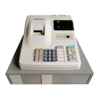
ER-A520/A530
– 3 –
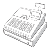
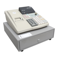
CHAPTER 3. REMOTE DRAWER:
ER-03DW, ER-04DW
1. OUTLINE
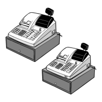
The ER-A520/530 allows connection of max, two remote drawers.
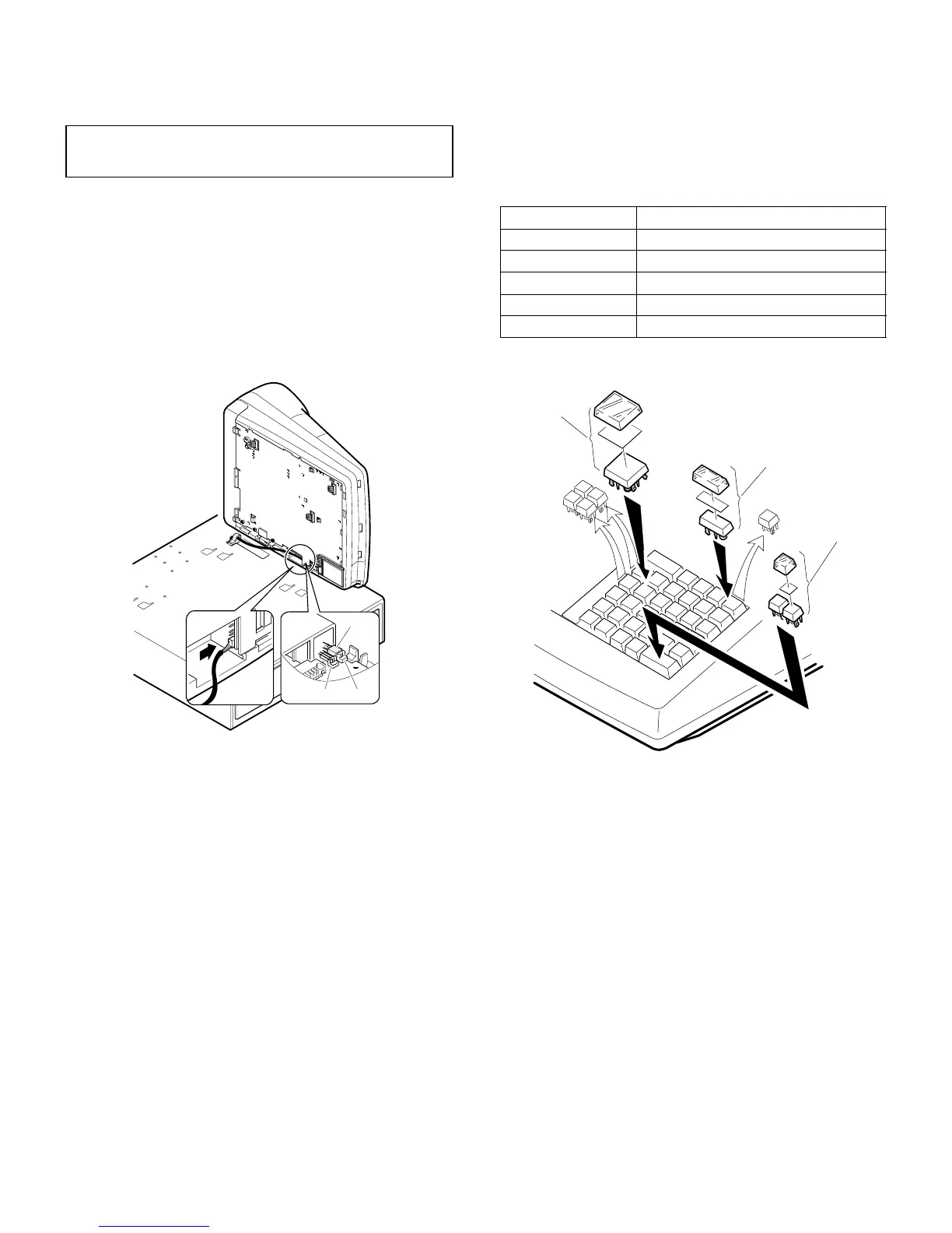
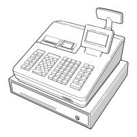
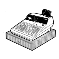
2. INSTALLATION PROCEDURE
1) Remove the top cabinet.
2) Connect the remote drawer cable 1 to the drawer connector on
the main PWB. (Location: CN7)
CHAPTER 4. KEY TOP KIT
(ER-A520 ONLY)
1. OUTLINE
The ER-A520 employs the following key top (option) to allow additional
installation of the key top and change in the key layout.
2. INSTALLATION PROCEDURE
CAUTION:
The drawer unit should be securely fitted to the supporting platform
to avoid instability when the drawer is open.
CN6 CN7
1
MODEL NAME DESCRIPTION
ER-11KT7 1 u 1 Key top
ER-12KT7 1 u 2 Key top
ER-22KT7 2 u 2 Key top
ER-11DK7G 1 u 1 Dummy key
ER-51DK7G 5 u 1 Dummy key
ER-22KT7
ER-12KT7
ER-11KT7