ER-A520/A530
– 2 –
CHAPTER 2. DISASSEMBLY
Caution: Before installation, be sure to turn off the power.
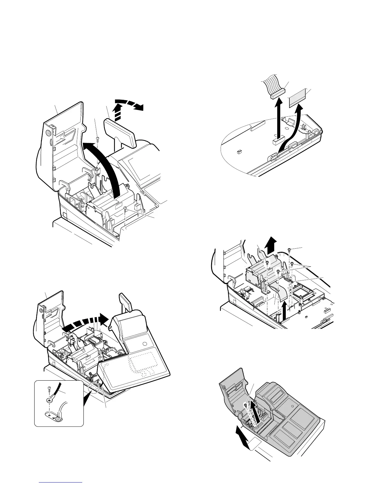
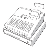
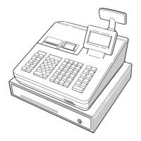
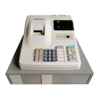
1. REMOVING THE TOP CABINET
1) Open the printer cover 1.
2) Lift the pop-up display unit 2.
3) Remove the two screws 3.
4) Slightly lift and slide the top cabinet, and remove the grounding
wire 4.
Note: Do not pull up the top cabinet unit the grounding wire and
connector cables from the top Cabinet are re-moved.
5) Remove the following cable 5 between the top cabinet and the
main PWB.
2. REMOVING THE PRINTER UNIT
1) Remove the top 1cabinet.
2) Remove the two screws 1 fixed on the printer unit.
3) Remove the screw 2 fixed on the earth wire 3.
4) Remove the printer cable 4 from the MAIN PWB (CN5).
3. REMOVING THE CABINET
1) Remove the cabinet fixing screw 1.
2) Slide the cabinet to the left, and remove the cabinet.
1
3
4
2
1
4
4
5
5
2
1
1
3
4
1