EasyManua.ls Logo

Sharp GF-8989H - User Manual

Sharp GF-8989H
48 pages
To Next Page IconTo Next Page
Loading...
SHARP
SERVICE
MANUAL
/SERVICE-ANLEITUNG/MANUEL
DE
SERVICE
@
APSS
Auto
Program
Search
System
G
F
-
8
9
8
9
H
GF-8989E
GF-8989H
/
GF-8989E
PHOTO:
GF-8989H
FOTO:
GF-8989H
PHOTOGRAPHIE:
GF-8989H
DiC
[eatevsvstem]
©
Noise
reduction
system
manufactured
under
licence
from
Dolby
Laboratories
Licensing
Corporation.
Dolby
and
tke
double-D
symbol
are
trademarks
of
Dolby
Laboratories
Liesnsins
Uurporation.
In
the
interests
of
user-safety
the
set
should
be
restored
to
its
original
condition
and
only
‘parts
identical
to
those
specified
be
used.
Rauschunterdriickungssystem
unter
Lizenz
der
Dolby
Laboratories
hergestellt.
“Dolby”
und
das
‘Doppel-D’’-
Symbol
sind
eingetragene
Warenzeichen
der
Dolby
Labora-
tories,
Im
Interesse
der
Benutzer-Sicherheit
sollte
dieses
Gerdt
wieder
auf
seinen
ursprtinglichen
Zustand
eingestellt
und
nur
die
feel
schriebenen
Teile
verwendet
werden.
|
Circuit
de
réduction
des
bruits
fabriqué
sous
licence
des
Dolby
Laboratories.
Le
mot
‘‘Dolby”
et
le
symbole
Double
D
sont
les
marques
de
fabrique
des
Dolby
Laboratories.
eer
AR
a
|
Dans
I’intérét
de
ta
sécurité
de
|'utilisateur,
‘appareil
devra
étre
reconstitué
dans
sa
condi-
tion
premiére
et
seules
des
piéces
identiques
a
celles
spécifiées,
doivent
étre
utilisées.
SHARP
CORPORATION
osaka,
JAPAN
Question and Answer IconNeed help?

Do you have a question about the Sharp GF-8989H and is the answer not in the manual?

Sharp GF-8989H Specifications

General IconGeneral
Number of Heads2
Signal-to-Noise Ratio50 dB
Tape Speed4.75 cm/s
Frequency Response40Hz - 12kHz (Normal Tape)
Wow and Flutter0.15 % (WRMS)
Speakers2 x 16 cm, 2 x 5 cm
Frequency Response (Metal Tape)40 Hz - 15, 000 Hz

Summary

SHARP GF-8989 H;GF-8989 HB Service Manual

General Safety Precautions

Important safety guidelines for operating and servicing the equipment.

Specifications and Technical Data

Technical Specifications Overview

Detailed technical data including power, speakers, dimensions, and frequency response.

Parts Identification

External Controls and Parts

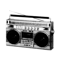
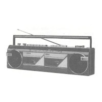
Identification and description of all front and rear panel controls and parts.

Initial Setup and Operation

Voltage Selection Procedure

Guide to setting the correct voltage input for safe operation.

Disassembly Guide

Removing Front Cabinet Assembly

Step-by-step instructions for removing the main front casing.

Mechanism Block Removal

Procedure for detaching the tape mechanism unit from the chassis.

Amp;Tuner;Control PWB Removal

Steps to remove the main circuit board assembly.

System Feature Explanations

APSS Operation Explained

Detailed explanation of the Auto Program Search System functionality.

ALC Operation Explained

Detailed explanation of the Automatic Level Control functionality.

Mechanical Adjustments

Pinch Roller Pressure Check

Procedure to verify and adjust pinch roller pressure.

Tape Torque Checks

Verifying torque in playback, fast forward, and rewind modes.

Pinch Roller Lever Gap Check

Checking the gap in the pinch roller lever mechanism.

Tape Speed Adjustment

Steps to adjust the tape playback speed.

Electrical Measurements and Adjustments

Head Azimuth Adjustment

Procedure to adjust the record/playback head azimuth for optimal performance.

Bias Oscillator Adjustment

Adjusting the record amplifier bias oscillator for correct recording.

Erase Current Check Procedure

Procedure to check and adjust the erase head current.

Playback Sensitivity Adjustment

Adjusting playback sensitivity for optimal tape reproduction.

Record;Playback Sensitivity Adjustment

Adjusting record and playback sensitivity levels for optimal signal levels.

Level Meter Display Calibration

Calibrating the level meter display for accurate visual indication.

General Alignment Guidelines

Alignment Procedure Overview

General guidelines and precautions for performing alignment tasks.

AM Band Alignment

AM IF;RF Alignment Steps

Detailed steps for aligning Intermediate Frequency and Radio Frequency circuits.

AM IF;RF Alignment Details

Specific parameters and connections for AM band alignment.

AM IF;RF Alignment Table

Table summarizing AM IF/RF alignment procedures and settings.

FM Band Alignment

FM IF;RF Alignment Steps

Detailed steps for aligning FM Intermediate Frequency and Radio Frequency circuits.

FM IF;RF Alignment Details

Specific parameters and connections for FM band alignment.

FM Stereo Alignment Procedure

Steps to align the FM stereo reception circuitry.

Schematic Diagram and Alignment Points

Alignment Point Locations

Identification of adjustment points on the printed circuit board.

Schematic Diagram Notes

Explanations of symbols, component markings, and measurement notes.

Component Notes and Symbol Definitions

Explanations for component types, values, and measurement conditions.

Component Replacement and Mechanical Tasks

Power IC (IC205) Replacement

Procedure for replacing the power integrated circuit.

Dial Cord Stringing Procedure

Instructions for correctly threading the dial cord.

Wiring Diagrams

Printed Wiring Board (PWB) Wiring

Diagram showing wiring connections on the main PWB.

PWB Wiring (Audio Section)

Detailed wiring diagram for the audio processing section.

PWB Wiring (Tuner Section)

Diagram showing wiring connections for the tuner section.

System Block Diagrams

Overall System Block Diagram

High-level overview of the unit's functional blocks and signal flow.

Schematic Diagrams

Tuner Section Schematic Diagram

Detailed circuit diagram for the tuner section of the receiver.

Exploded Views

Cabinet Assembly Exploded View

Diagram illustrating the assembly of the unit's outer casing.

Integrated Circuit (IC) Details

IC Block Diagrams and Circuits

Diagrams and equivalent circuits for key integrated circuits.

Component Specifications

Transistor and LED Types

Identification and diagrams for transistors and LEDs used in the unit.

Packaging and Shipping Information

Packing Method Details

Instructions for packing the unit for shipment.

Replacement Parts List

Transistors, Diodes, and ICs

List of replacement transistors, diodes, and integrated circuits.

Controls, Coils, Transformers, Filters

Replacement parts list for controls, coils, transformers, and filters.

Capacitors and Resistors

Replacement parts list for capacitors and resistors.

Resistors List

Detailed list of replacement resistors.

Mechanical Parts and Miscellaneous

Replacement parts for mechanical components and miscellaneous items.

Miscellaneous Parts

List of miscellaneous parts including knobs, switches, and connectors.

More Miscellaneous Parts

Additional miscellaneous parts like handles, covers, and cables.

AC Supply Leads and Connectors

Replacement parts list for AC supply leads and connectors.

AC Supply Leads and Labels

Additional AC supply leads and related labels.

Model Specific Differences

GF-8989 H vs GF-8989 HB Part Number Differences

Table detailing specific part number variations between models.

GF-8989 H vs GF-8989 HB Label and Manual Differences

Differences in labels, manuals, and cartons between models.

Related product manuals