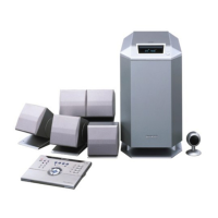
HT-CN300
– 6 –
Top Cover A
LCD Cover
Top Cover B
Back Cover R
Back Cover L
(A1)x2
ø3x8mm
(B1)x2
ø2.5x12mm
(D1)x6
ø3x8mm
1 Top Cover B 1. Screw ...................... (A1) x2 6-1
2 LCD Cover 1. Hexagon Screw ...... (B1) x2 6-1
3 Top Cover A/ 1. Screw ...................... (C1) x4 6-2
LCD PWB 2. Flat Cable ............... (C2) x3
3. Screw ...................... (C3) x4
4 Back Cover L/R/ 1. Screw .................... (D1) x25 6-1, 7-1
Rear Panel
5 DSP PWB 1. Screw ...................... (E1) x2 7-2
2. Socket ..................... (E2) x1
3. Flat Cable ............... (E3) x4
4. PWB Holder ............ (E4) x2
6 Subwoofer Stand/ 1. Screw .......................(F1) x4 7-2
PWB Unit 2. Screw .......................(F2) x2
3. Socket ......................(F3) x1
7 Video PWB 1. Screw ...................... (G1) x3 7-3
2. Socket ..................... (G2) x2
8 Audio PWB 1. Screw...................... (H1) x2 7-3
9
AMP. PWB
1. Screw ....................... (J1) x6 7-3
2. Socket ...................... (J2) x4
10 Speaker PWB 1. Screw ...................... (K1) x1 7-3
11 Subwoofer 1. Screw .......................(L1) x4 7-2
DISASSEMBLY
Figure 6-2
STEP REMOVAL PROCEDURE FIGURE
Figure 6-1
HT-CN300
HT-CN300
DSP PWB
LCD PWB
Top Cover A
(C3)x4
ø3x8mm
(C1)x2
ø4x12mm
(C1)x2
ø4x20mm
(C2)x3
Caution on Disassembly
Follow the below-mentioned notes when disassembling
the unit and reassembling it, to keep it safe and ensure
excellent performance:
1. Be sure to remove the power supply plug from the wall
outlet before starting to disassemble the unit.
2. Take off nylon bands or wire holders where they need to
be removed when disassembling the unit. After servicing
the unit, be sure to rearrange the leads where they were
before disassembling.
3. Take sufficient care on static electricity of integrated
circuits and other circuits when servicing.