E-5
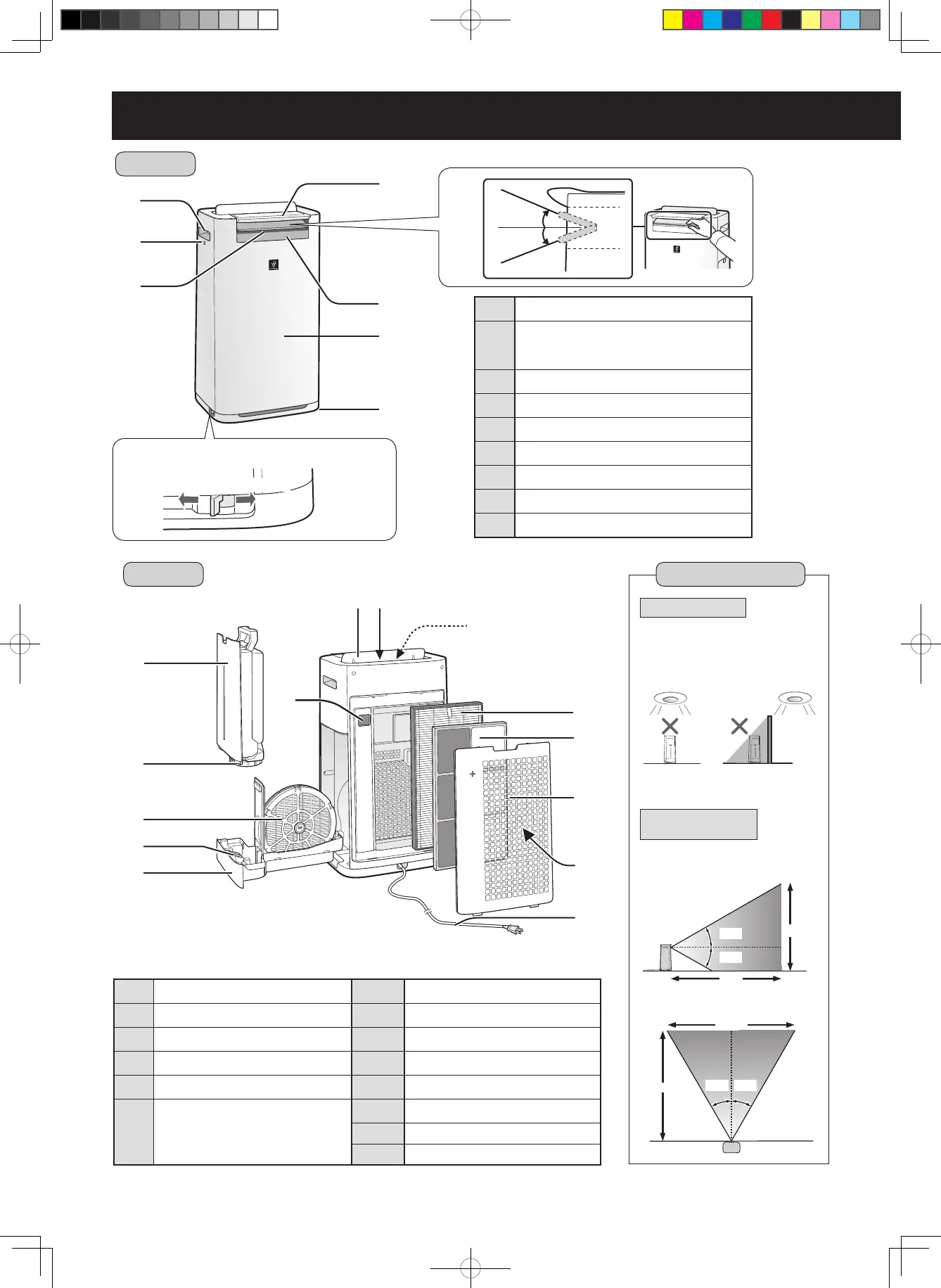
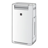
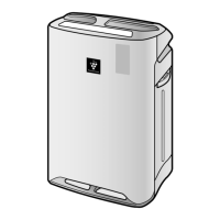
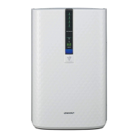
PART NAMES
FRONT
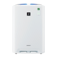
BACK
1
Handle (2 Locations)
2
Sensor (Internal)
Temperature / Humidity / Odor*
(*KC-G60 / KC-G50)
3
Air Outlet (Front)
4
Caster Stopper (Right & Left)
5
Operation Panel
6
Front Louver (Adjustable)
7
Front Display
8
Unit
9
Caster (4 Locations)
1
Water Tank
7
Back Louver
2
Tank Cap
8
Air Outlet (Back)
3
Humidifying Filter
9
Air Outlet LED(White)
4
Float
10
HEPA Filter
5
Humidifying Tray
11
Deodorizing Filter
6
Dust(sensitive) Sensor /
Sensor Filter
12
Back Panel (Pre-Filter)
13
Air Inlet
14
Power Cord / Plug
To Lock a caster stopper (Right & Left)
Locked
Unlocked
Front
20°
20°
1
3
5
2
4
10
11
12
13
7
8
9
6
7
8
9
5
1
2
3
4
6
14
Detection range
Light Sensor
Motion Sensor
(KC-G60 / KC-G50)
Do not install the unit in the
following places.
The Light Sensor may not sense
correctly.
Sensory range is the area shown
below.
1.6m
2m
30°
30°
2.3m
2m
30° 30°
Front
Right and Left
Directly under
a light xture.
In shadow
(Plug shape varies by country.)
KC-G60TA_G50TA_G40TA.indd 5 2017/05/23 16:26:50