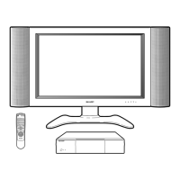
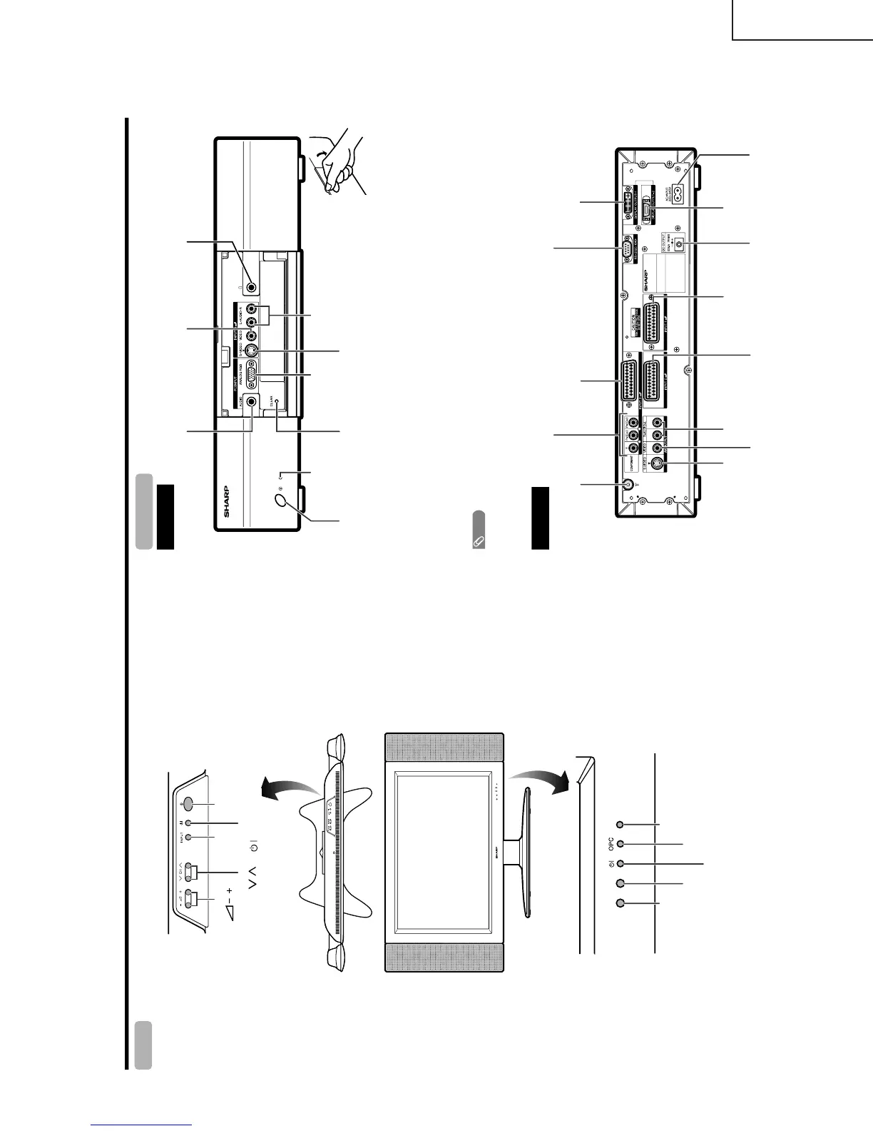
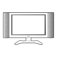
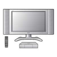
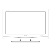
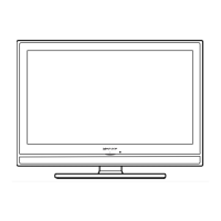
Part names
OPC indicator*
STANDBY/ON indicator
MAIN POWER
button
OPC sensor
Remote control sensor
indicator
Display
STANDBY/ON button
(
)
INPUT
button
VOLUME buttons
(
/
)
CHANNEL buttons
(CH
/
)
Remote control sensor
*OPC: Optical Picture Control
INPUT 1 terminal
(SCART)
INPUT 3 terminals (Y, P
B
(C
B
)
,
P
R
(C
R
))
INPUT 2 terminal (SCART)
AV OUTPUT terminal
(S-VIDEO)
DISPLAY OUTPUT1 terminal
AC INPUT terminal
CLEAR*
POWER button
RS-232C terminal
INPUT 4 terminal (S-VIDEO)
PC INPUT terminal (AUDIO)
INPUT 4 terminals (AUDIO)
INPUT 3 terminal (SCART)
AV OUTPUT terminal
(VIDEO)
AV OUTPUT terminals
(AUDIO)
PC INPUT terminal
(ANALOG RGB)
* If the AVC System is switched on but it does not appear to be operating correctly, it may need resetting. In this
case, press CLEAR, shown in the diagram, lightly with the end of a ballpoint pen or other pointed object.
This will reset the System as shown below.
• AV MODE resets to USER.
• TV channel resets to channel 1.
• Dual screen resets to normal.
• Audio setting initialises.
• SRS resets to OFF.
• Image position is initialised.
NOTE
• Pressing CLEAR will not work if the System is in standby mode (indicator lights red).
• Pressing CLEAR will not delete channel preset or password. See page 60 for clearing the password when you know it.
See page for initialising to the factory preset values when you forget your password.
ANTENNA INPUT terminal
AVC System
STANDBY/ON indicator
DISPLAY OUTPUT2
terminal
INPUT 4 terminal (VIDEO)
(How to open the door)
Front view
Rear view
Headphone
DC OUTPUT terminal
(Terminal for expanded
functionality in the near
future.)
(When connecting headphones,
the sound from the speakers is
muted.)