EasyManua.ls Logo

Sharp LC-30HV4U User Manual

Sharp LC-30HV4U
254 pages
To Next Page IconTo Next Page
Page #1 background imageLoading...
Page #1 background image
LC-30HV4U
LC-30HV4D
SERVICE MANUAL
In the interests of user-safety (Required by safety regulations in some countries) the set should be restored
to its original condition and only parts identical to those specified should be used.
CONTENTS
Page
LCD COLOR TELEVISION
» IMPORTANT SERVICE SAFETY PRECAUTION ..... 2
» SPECIFICATIONS................................................ 5
» OPERATION MANUAL ........................................ 6
» DIMENSIONS .................................................... 12
» REMOVING OF MAJOR PARTS........................ 14
»
ADJUSTMENT PROCEDURES (AVC System) ..
21
» UPGRADING INSTALLED PROGRAMS ........... 33
» ADJUSTMENT PROCEDURES (Display) ......... 35
» MAJOR IC INFORMATIONS ..............................39
» TROUBLE SHOOTING TABLE .......................... 60
» CHASSIS LAYOUT............................................. 70
» SYSTEM BLOCK DIAGRAM (AVC System) ...... 74
» SIGNAL FLOW BLOCK DIAGRAM
(AVC System)..................................................... 76
Page
» POWER SYSTEM BLOCK DIAGRAM
(AVC System)..................................................... 78
» PC I/F BLOCK DIAGRAM (AVC System) .......... 80
» SIGNAL BLOCK DIAGRAM (Display) ................ 82
» POWER UNIT BLOCK DIAGRAM (Display) ...... 84
» OVERALL WIRING DIAGRAM (AVC System) ... 86
» OVERALL WIRING DIAGRAM (Display)............ 90
» DESCRIPTION OF SCHEMATIC DIAGRAM ..... 92
» WAVEFORMS .................................................... 93
» SCHEMATIC DIAGRAM..................................... 94
» PRINTED WIRING BOARD ASSEMBLIES...... 169
» PARTS LIST ..................................................... 213
» PACKING OF THE SET ................................... 253
SHARP CORPORATION
This document has been published to be used for
after sales service only.
The contents are subject to change without notice.
LC-30HV4U
LC-30HV4D
S33Y2LC30HV4U
MODELS
Question and Answer IconNeed help?

Do you have a question about the Sharp LC-30HV4U and is the answer not in the manual?

Sharp LC-30HV4U Specifications

General IconGeneral
Screen Size30 inches
Display TypeLCD
Resolution1280 x 768
Aspect Ratio16:9
Backlight TypeCCFL
HDMI Ports1
USB Ports0
Contrast Ratio800:1
Brightness450 cd/m²
Viewing Angle170° (H) / 170° (V)
Response Time16 ms
Input PortsComponent, Composite, S-Video
Weight39.7 lbs (with stand)
Speakers2 x 10W

Summary

IMPORTANT SERVICE SAFETY PRECAUTION

BEFORE RETURNING THE RECEIVER (Fire & Shock Hazard)

Checks to ensure the unit is safe before returning to the user.

SAFETY NOTICE

Highlights special safety characteristics of parts, identified by symbols.

Precautions for using lead-free solder

SPECIFICATIONS

OPERATION MANUAL

Part names

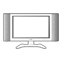
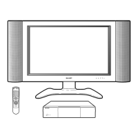
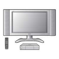
Identifies and labels external and internal parts of the TV and AVC system.

Front view

Illustrates and labels the front panel controls and indicators.

Rear view

Illustrates and labels the rear panel terminals and connections.

Setting the System

Provides instructions for connecting system cables and AC power for initial setup.

REMOVING OF MAJOR PARTS

AVC System Parts Removal

Details the step-by-step procedure for disassembling the AVC system.

Display Parts Removal

Details the step-by-step procedure for disassembling the display unit.

ADJUSTMENT PROCEDURES (AVC SYSTEM)

Preparation for adjustment

Prepares for adjustment by noting factory settings and using a stable power supply.

How to enter the in-process adjustment mode

Steps to access the special adjustment mode by pressing specific buttons simultaneously.

ADJUSTMENT PROCEDURES (Display)

Analog adjustment

Procedures for analog adjustments like voltage and bias.

Tuner adjustment

Procedures for adjusting tuner signal settings and levels.

NTSC signal adjustment

Procedures for adjusting NTSC signal parameters like contrast and color gain.

Digital white balance adjustment

Adjusts digital signal parameters for optimal white balance.

Factory setting

MAJOR IC INFORMATIONS

IC Details

Provides information on major integrated circuits and their functions within the product.

TROUBLE SHOOTING TABLE

(AVC System)

Step-by-step guide to diagnose and resolve power-on and no-sound issues in the AVC system.

(Display)

Guide for diagnosing and resolving display issues like no power, no picture, or no sound.

SYSTEM BLOCK DIAGRAM (AVC System)

SIGNAL FLOW BLOCK DIAGRAM (AVC System)

POWER SYSTEM BLOCK DIAGRAM (AVC System)

PC I/F UNIT BLOCK DIAGRAM (AVC System)

SIGNAL BLOCK DIAGRAM (Display)

POWER UNIT BLOCK DIAGRAM (Display)

OVERALL WIRING DIAGRAM-1/2 (AVC system)

OVERALL WIRING DIAGRAM-2/2 (AVC system)

OVERALL WIRING DIAGRAM (Display)

DESCRIPTION OF SCHEMATIC DIAGRAM

VOLTAGE MEASUREMENT CONDITION

Specifies conditions for measuring voltage values using a color bar signal.

WAVEFORM MEASUREMENT CONDITION

Specifies conditions for observing waveforms using a color bar signal.

INDICATION OF RESISTOR & CAPACITOR

Explains symbols for resistors and capacitors, including tolerance and type.

IMPORTANT SAFETY NOTICE

Highlights safety-critical parts marked with 'å' that must be replaced with specified ones.

WAVEFORMS

PARTS LIST

PARTS REPLACEMENT

Explains how to order parts and identifies safety-critical components.

PRINTED WIRING BOARD ASSEMBLIES

Lists assemblies that are not individual replacement items.
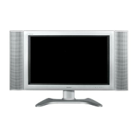
Related product manuals