24
LC-30HV4U
LC-30HV4D
(2) Tuner adjustment
Item Adjusting conditions/points Adjusting procedure
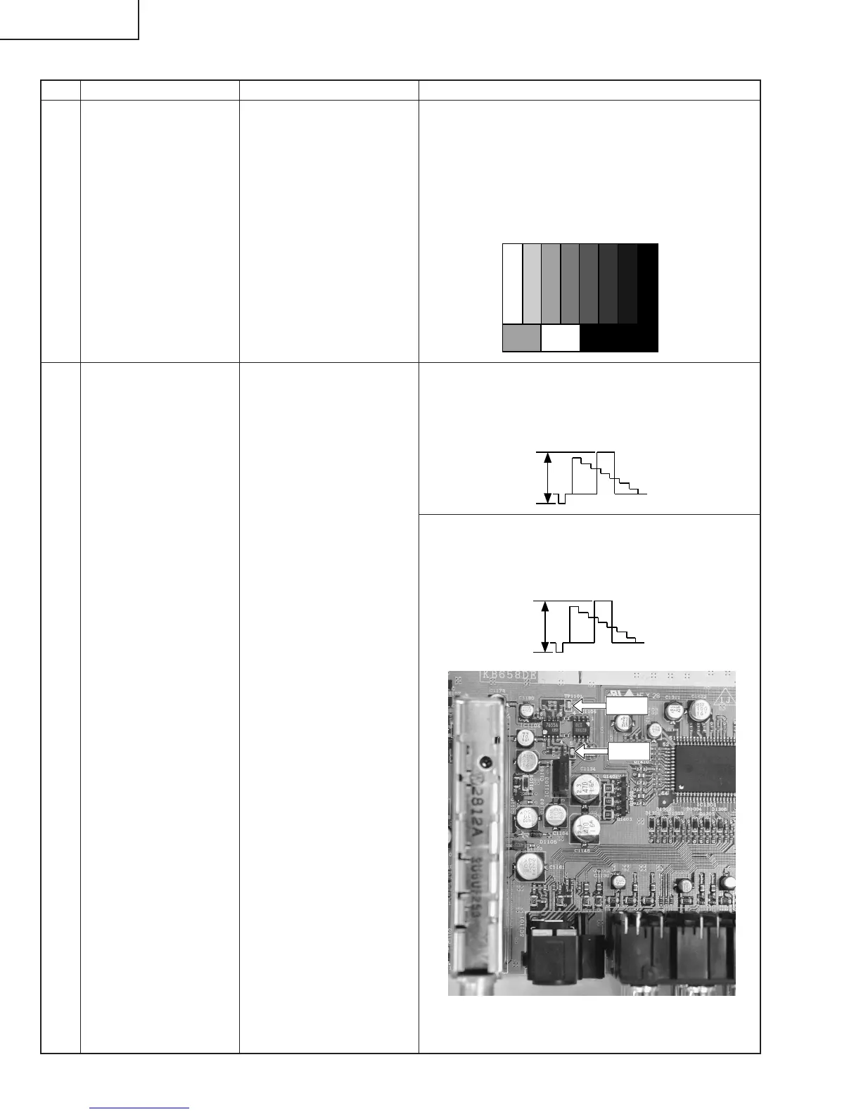
1 Signal setting Signal: • Use a signal generator to provide the tuner with a
NTSC RF Signal RF signal of 193.25 MHz on the split field color bar.
(Split field color bar)
•
The color saturation of the color bar must be 75%.
Input terminals:
A 100% white area must be included.
ANT-A, ANT-B • Make sure the 100% white area (synchronized)
US channel 10 received shows 2.00 Vp-p when the color bar opens in
video mode. If not, adjust the signal generator.
2 Tuner level Adjustment Page: 4 1.Provide the above RF signal to ANT-A and adjust
Locations: TP1101, TP1102
"TUNER DAC ADJ" so that the tuner output is
1.0 ± 0.02 Vp-p at TP1101 when US channel 10 is
received.
1.0Vp-p
2.Provide the above RF signal to ANT-B and adjust
"TUNER B DAC ADJ" so that the tuner output is
1.0 ± 0.02 Vp-p at TP1102 when US channel 10 is
received.
TP1101
TP1102
1.0Vp-p