LC32D44E/S/RU-BK/GY (1st Eddition)
5 – 16
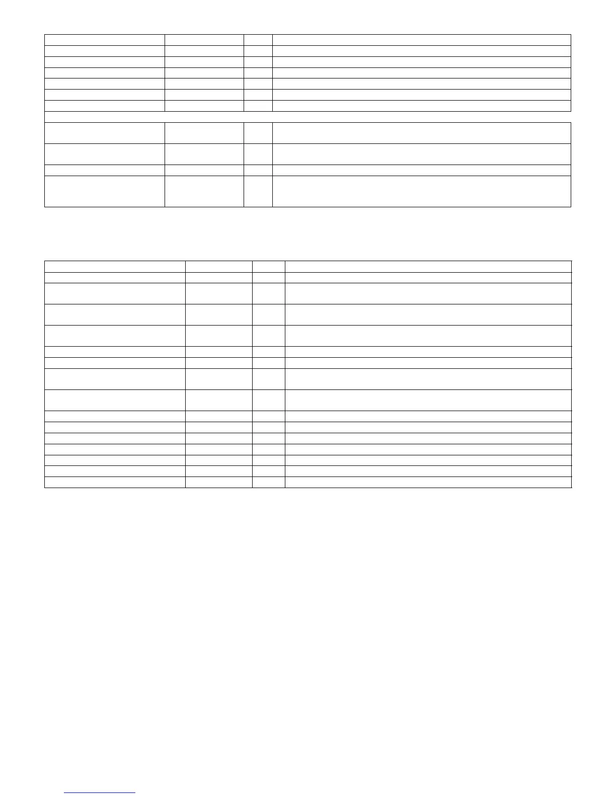
11. IC4201 (RH-IXB765WJQZQ)
This IC is 256Mb H-die DDR SDRAM (static dynamic random-access memory) IC.
In this equipment, it is used for LMI memory (for image processing), and data is used for operation of the Set-top-box decoder.
184 VDDDLL --- 1.2 V for DLL.
185 GNDDLL --- Ground for DLL.
176 VDDDE0 --- 1.2 V for delay element 1.
177 VSSDE0 --- Ground for delay element 1.
196 VDDDE1 --- 1.2 V for delay element 2.
195 VSSDE1 --- Ground for delay element 2.
Digital power supply pins
8, 47, 67, 101, 124, 155, 173,
204
VDD12 --- 1.2 V digital power supply.
151, 158, 165, 170, 179, 187,
193, 200, 207, 212
VDD25 --- 2.5 V power supply when connected to DDR SDRAM on the LMI interface.
3, 42, 55, 72, 84, 96, 113, 129 VDD33 --- 3.3 V power supply.
EP1, 9, 27, 48, 54, 68, 102,
112, 125, 136, 156, 161, 172,
189, 205
GND --- Ground.
Pin No. Pin Name I/O Pin Function
45, 46 CK, CK I Clock : CK and CK are differential clock inputs.
44 CKE I
Clock Enable : CKE HIGH activates, and CKE LOW deactivates internal clock
signals, and device input buffers and output drivers.
24 CS I
Chip Select : CS enables (registered LOW) and disables (registered HIGH) the
command decoder.
23-21 RAS, CAS, WE I
Command Inputs : RAS, CAS and WE (along with CS) define the command
beingentered.
20, 47 LDM, (UDM) I Input Data Mask.
26, 27 BA0, BA1 I Bank Addres Inputs.
29, 30, 31, 32, 35, 36, 37, 38, 39, 40,
28, 41, 42
A [0:12] I Address Inputs.
2, 4, 5, 7, 8, 10, 11, 13, 54, 56, 57,
59, 60, 62, 63, 65
DQ[0:15] I/O Data Input/Output : Data bus.
16, 51 LDQS, (U)DQS I/O Data Strobe : Output with read data, input with write data.
14, 17, 19, 25, 43, 50, 53 NC --- No Connect : No internal electrical connection is present.
3, 9, 15, 55, 61 VDDQ --- DQ Power Supply.
6, 12, 52, 58, 64 VSSQ --- DQ Ground.
1, 18, 33 VDD --- Power Supply.
34, 48, 66 VSS --- Ground.
49 VREF I SSTL_2 reference voltage.
Pin No. Pin Name I/O Pin Function