LC-60/70EQ10U,SQ10U/15U/17U,TQ15U,UQ17U
4 – 19
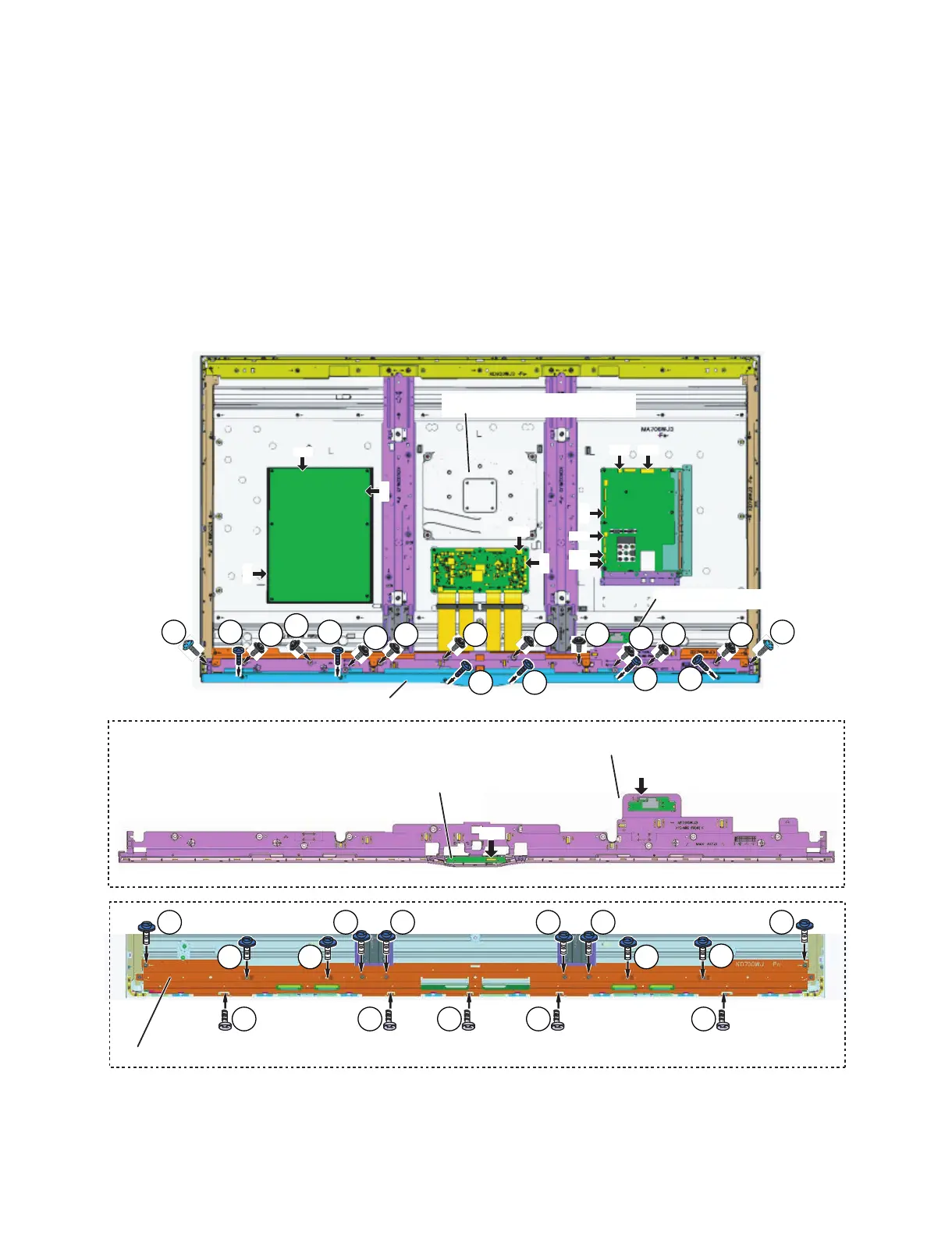
3. 3. Removeing of connectors and Decoration Cover (Rear), Front Cover Ass'y and BL Support Angle Ass'y
(Bottom).
1. Disconnect the following connectors from MAIN Unit. (SP2,PD, LW, RA, UB, BT).
2. Disconnect the following connectors from POWER/DRIVE Unit. (PD, L1).
3. Disconnect the following connectors from LCD CONTROL Unit. (PL, LW).
4. Remove the 2 lock screws (2), 10 lock screws (3) and detach the Front Cover Ass'y (4).
5. Remove the 6 lock screws (1) and detach the Decoration Cover (Rear) (10).
6. Disconnect the following connector from WiFi+BT Unit. (UB)
7. Detach the WiFi+BT Unit (6) from the Front Cover Ass'y.
8. Disconnect the following connector from RC/ICON Unit. (RA).
9. Detach the RC/ICON Unit (5) from the Front Cover Ass'y.
10.Remove the 5 lock screws (8), 10 lock screws (7) and detach the BL Support Angle Ass'y (Bottom) (9).
11.Detach the Speaker Unit (Woofer) (11).
PDSP2
RA
UB
BT
LW
AC
LW
PL
PD
L1
ԡDecoration Cover (Rear)
ԜRC/ICON Unit
RA
ԝWiFi+BT Unit
UB
٨ԛFront Cover Ass'y
Ԡ$.5WRRQTV#PING#UU[$QVVQO
ԛFront Cover Ass'y
ԢSpeaker Unit (Woofer)
䎔
䎖 䎖 䎖 䎖 䎖 䎖 䎖
䎕 䎕䎔
䎔 䎔
䎔䎔
䎚 䎚 䎚 䎚 䎚 䎚
䎚
䎚䎚䎚
䎛 䎛 䎛 䎛 䎛
䎖
䎖
䎖
 Loading...