Do you have a question about the Sharp LC-60LE745U and is the answer not in the manual?
Essential safety guidelines for service technicians performing repairs.
Checks and hazards to address before returning the unit to the user.
Information on safety characteristics of parts and replacement precautions.
Information on using lead-free solder and identifying the LF symbol.
Guidelines for applying and soldering with lead-free wire.
List of Printed Wiring Board assemblies with part codes.
List of other service parts like LCD Panel Modules.
Specific ICs for service use, including monitor microprocessors.
List of required service jigs and connecting cords.
Technical specifications including size, resolution, functions, terminals, and power.
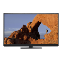
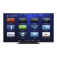
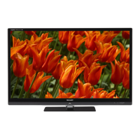
Identification of front and side physical parts of the TV.
Identification of rear physical parts and connectors of the TV.
Detailed labeling and function of each button on the remote control.
Step-by-step instructions for attaching the stand to 70" models.
Step-by-step instructions for attaching the stand to 60" models.
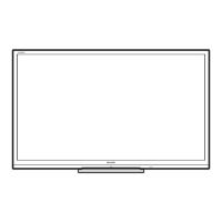
Visual representation of the physical dimensions for 70" TV models.
Visual representation of the physical dimensions for 60" TV models.
Steps to remove stand unit and rear cabinet for 60" models.
Cautions for proper assembly to avoid clearances between cabinet parts.
Steps to remove bottom cover, speaker units, and key unit.
Instructions for disconnecting various connectors from main units.
Steps to remove power, main, and LCD control units.
Steps to remove RF units, Wi-Fi, ICON units, and decorative covers.
Steps to remove stand unit and rear cabinet for 70" models.
Cautions for proper assembly between CAB-A and CAB-B for 70" models.
Steps to remove bottom cover and key unit for 70" models.
Instructions for disconnecting connectors from main units for 70" models.
Steps to remove speaker, LCD control, main, and power/driver units for 70" models.
Steps to remove covers, IR, Wi-Fi, ICON units, and speaker unit for 70" models.
Location for applying heat measure sheet on main PWB and LCD control unit.
Precautions for mounting main PWB and ensuring EMI-prevention parts are correctly placed.
Diagram showing main PWB mounting and access holes for confirmation.
Procedures after replacing PWB units or ICs, including software updates.
Steps to upgrade main and monitor microprocessor software using USB memory.
Detailed steps for upgrading software and interpreting upgrade screens.
Steps for upgrading monitor microprocessor software and performing Industry Init.
Procedures to enter and exit the adjustment process mode.
List of adjustment items and their descriptions across different pages.
Continuation of adjustment items, including analog RGB, component, and tuner adjustments.
Continuation of adjustment items, including test patterns and version checks.
Continuation of adjustment items, including WiFi settings and error cause resets.
Explanation of normal and error standby cause codes and their meanings.
Checks for adjustment jig, signal source, and signal levels.
Procedures for adjusting composite N358 signal and tuner input.
Steps for adjusting component 33K signal.
Steps for adjusting analog RGB signal.
Steps for adjusting tuner and V-CHIP.
Detailed steps and parameters for white balance adjustment.
Procedures for writing MAC and Netflix/WMDRM keys.
Steps to configure factory settings and initialize unit parameters.
Methods to enter the public mode setup screen using specific key combinations.
List and explanation of configurable settings within the Public Mode menu.
Configuration for power-on behavior and volume limits.
Configuration for panel buttons, menu buttons, and OSD display.
Configuration for input mode selection and loud speaker output.
Setting to enable or disable public mode functionality.
Using the center icon LED to diagnose failures.
Table detailing slow and fast flashing patterns for various error types.
Specific LED flashing sequences for inverter, power, and communication failures.
LED flashing details for monitor temperature and main failures.
Flowchart for diagnosing issues when the LED backlight does not turn on.
Flowchart for diagnosing issues after replacing C-S FPC or C-PWB.
Diagnosing display issues related to the LCD controller board.
Diagnostic steps for no video on HDMI INPUT-1.
Diagnostic steps for no video on HDMI INPUT-2.
Diagnostic steps for no video on HDMI INPUT-3.
Diagnostic steps for no video on HDMI INPUT-4.
Diagnostic steps for no video on COMPONENT INPUT-5.
Diagnostic steps for no video on COMPOSITE INPUT-6.
Diagnostic steps for no video on COMPOSITE INPUT-7.
Diagnostic steps for no video on PC INPUT-8.
Diagnostic steps for no video on UHF/VHF broadcast reception.
Diagnostic steps for no video on digital broadcast reception.
Diagnostic steps for no video via MHL connection on INPUT-4.
Diagnostic steps for no audio on inputs 5, 6, and 7.
Diagnostic steps for no audio on PC INPUT-8.
Diagnostic steps for no audio on HDMI INPUT-2.
Diagnostic steps for no audio during UHF/VHF broadcast reception.
Diagnostic steps for no audio during digital broadcast reception.
Diagnostic steps for no audio on HDMI inputs 1-4.
Steps to check SPDIF signal output for digital audio.
Steps to check audio signal outputs from the monitor.
Details of the 5-input, 1-output HDMI port processor IC.
Information on the audio amplifier IC for line-out/headphone.
Details of the Audio DSP IC with digital audio adjustment functions.
Diagram showing the overall wiring connections for 60" models.
Diagram showing the overall wiring connections for 70" models.
Comprehensive block diagram illustrating the system architecture and component interactions.
List of sections within the parts guide, including PWB assemblies and cabinet parts.
List of PWB assemblies with part codes and descriptions.
List of LCD panel module units with part codes.
Illustrated breakdown of cabinet parts for 60" models.
Detailed list of cabinet parts, including screws and covers.
Illustrated breakdown of cabinet parts for 70" models.
Detailed list of cabinet parts, including screws and covers for 70" models.
List and diagram of supplied accessories and packing materials for 60" models.
Detailed list of supplied accessories and packing parts for 60" models.
List and diagram of supplied accessories and packing materials for 70" models.
Detailed list of supplied accessories and packing parts for 70" models.
| Display diagonal | 60 \ |
|---|---|
| Native aspect ratio | 16:9 |
| Native refresh rate | 120 Hz |
| LED backlighting type | Edge-LED |
| Supported video modes | 1080p |
| Contrast ratio (dynamic) | 8000000:1 |
| Viewing angle, horizontal | 176 ° |
| 3D | Yes |
| 3D type | Active |
| Analog signal format system | NTSC |
| Digital signal format system | ATSC |
| RMS rated power | 20 W |
| Number of speakers | 2 |
| DVI port | No |
| HDMI ports quantity | 4 |
| DVI-D ports quantity | 0 |
| USB 2.0 ports quantity | USB 2.0 ports have a data transmission speed of 480 Mbps, and are backwards compatible with USB 1.1 ports. You can connect all kinds of peripheral devices to them. |
| Digital audio optical out | 1 |
| Electronic Program Guide (EPG) | - |
| Product color | Black |
| AC input voltage | 120 V |
| AC input frequency | 60 Hz |
| Power consumption (max) | 170 W |
| Power consumption (standby) | - W |
| Depth (with stand) | 366 mm |
|---|---|
| Height (with stand) | 887 mm |
| Weight (with stand) | 34500 g |
| Depth (without stand) | 55 mm |
| Width (without stand) | 1390 mm |
| Height (without stand) | 838 mm |
| Weight (without stand) | 27500 g |