MX-C250 ADJUSTMENTS 5 – 10
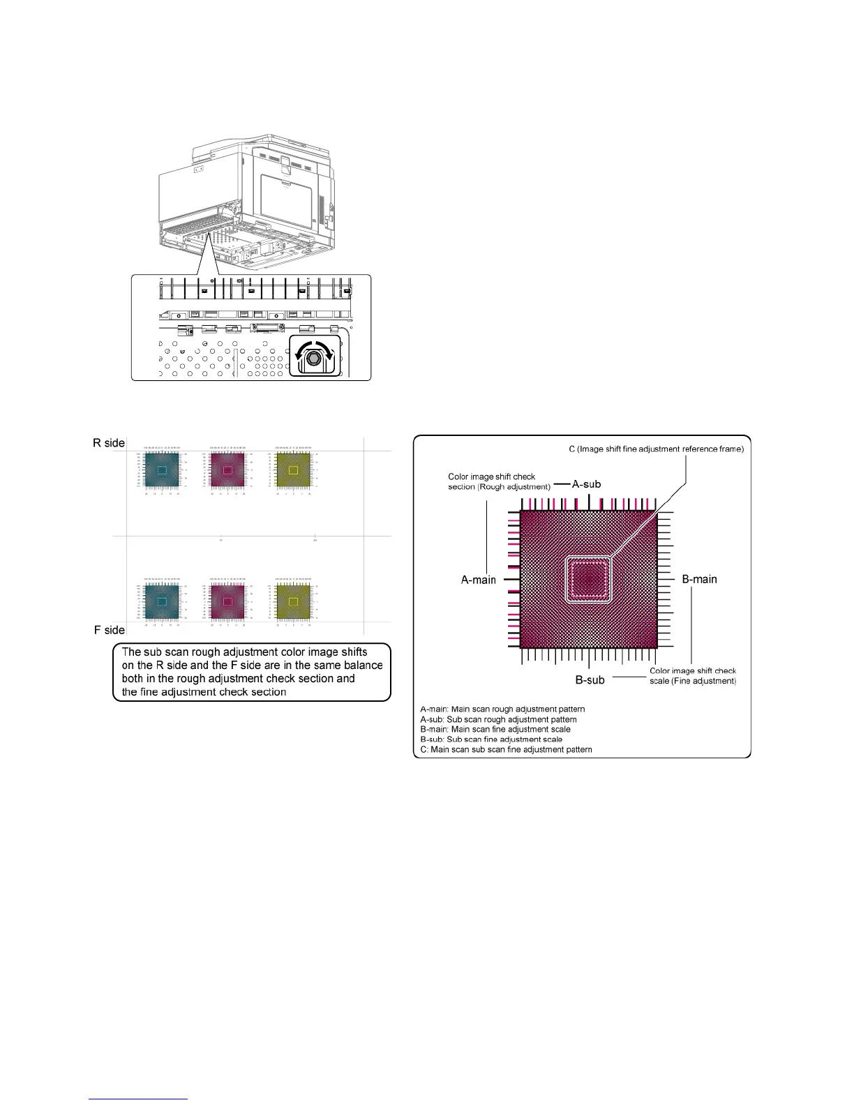
9) If there are several skewed areas on the test printing result, turn
all the LSU skew adjustment screws shown in the figure * To make
"SKEW_*" values in the following ranges, turn the LSU skew
adjustment screws clockwise direction (a) or counterclockwise
direction (b).
SKEW_C : +/-30, SKEW_M : +/-40, SKEW_C : +/-20
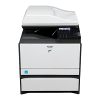
10) Enter the SIM61-4 mode and perform the procedures of 2) - 3).
Check the printed color image skew pattern.
In each Y/M/C color print pattern printed separately in the F
side and in the R side, note the same print color pattern and
check to confirm that the front frame side and the rear frame
side are in the same condition.
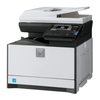
Rough adjustment pattern check:
Check the sub scan rough adjustment color image shift check
section on the R side and the F side of each color, use the
black scale of "0" as the center reference, and check the bal-
ance in shifts of the color image line positions in the positive
and the negative directions. The balance in the R side must be
the same as that in the F side.