MX-C250 ADJUSTMENTS 5 – 24
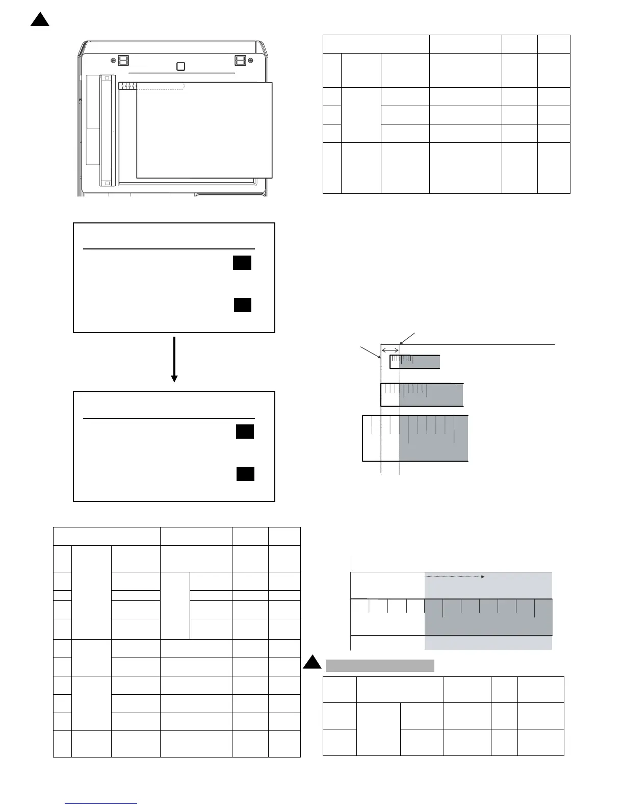
2) Enter the SIM 50-1 mode.
3) Set RRCA, LEAD, and SIDE to the default values.
4) Perform the image lead edge reference position adjustment.
Shift to the copy mode, and make a copy at each of 100% and
200% in the document table mode.
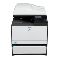
When the adjustment value of RRCA is proper, the lead edge
image from 4.0mm is not copied in either of 100% and 200%
copy scale.
If not, change and adjust the RRCA value.
(Adjust so that the lead edge image from 4.0mm is not copied
in either of different copy magnification ratios.)
Repeat the above procedures until a satisfactory result is
obtained.
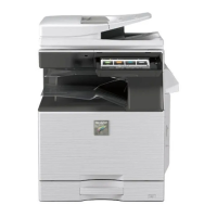
5) Image loss adjustment
When the adjustment item of the image loss below is set to the
default value, it is adjusted to the standard state. If it is not in
the below standard state, or when it is set to a desired value,
change these adjustment items.
Image loss: 4.0mm
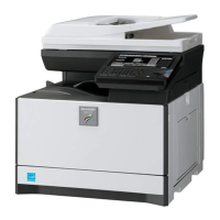
Item/Display Content
Setting
range
Default
value
1
Lead
edge
adjust-
ment
value
RRCA
Document lead
edge reference
position (OC)
0 to 99 50
2 RRCB-CS1
Regis-
tra-
tion
motor
ON
timing
adjust-
ment
Standard
Tray
1 to 99 40
3 RRCB-DSK Desk 1 to 99 50
4 RRCB-MFT
Manual
paper feed
1 to 99 50
5 RRCB-ADU ADU 1 to 99 50
6
Image
loss area
setting
value
LEAD
Lead edge image
loss area setting
0 to 99 10
7SIDE
Side image loss
area adjustment
0 to 99 10
8
Void area
adjust-
ment
DENA
Lead edge void
area adjustment
1 to 99 40
9DENB
Rear edge void area
adjustment
1 to 99 35
10
FRONT/
REAR
FRONT/REAR void
area adjustment
1 to 99 35
11
Off-cen-
ter adjust-
ment
OFFSET_
OC
OC document off-
center adjustment
1 to 99 50