MX-C250 ADJUSTMENTS 5 – 19
ADJ 6 Scan image magnification ratio
adjustment
(Manual adjustment)
Only when the manual adjustment is required, execute this adjust-
ment.
In other words, this manual adjustment is executed when a satis-
factory result is not obtained from the automatic adjustment (ADJ
4).
6-A Scan image magnification ratio adjustment
(main scanning direction) (Manual
adjustment) (Document table mode)
If the default adjustment value of the scan image magnification
ration adjustment (main scanning direction) of SIM 48-1, copy
image quality may be degraded. Therefore, this adjustment must
be executed only when there is a special necessity.
This adjustment must be performed in the following cases:
* When the copy magnification ratio in the copy image main scan-
ning direction is not properly adjusted.
* When the scanner motor is replaced.
* U2 trouble has occurred.
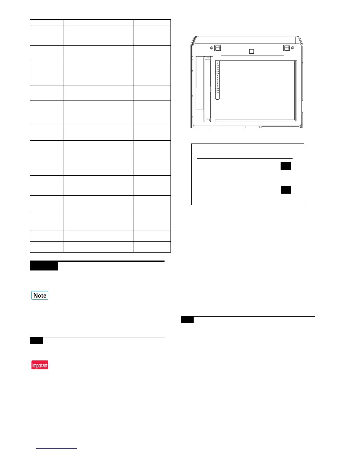
1) Place a scale on the document table as shown in the figure
below.
2) Enter the SIM 48-1 mode.
3) Make a normal copy and obtain the copy magnification ratio.
Press [CLOSE] key to shift from the simulation mode to the
copy mode, and make a copy.
4) Check that the copy magnification ratio is within the specified
range (100 +/- 1.0%).
If the copy magnification ratio is within the specified range (100
+/-1.0%), the adjustment is completed. If the copy magnifica-
tion ratio is not within the specified range, perform the follow-
ing procedure.
5) Change the CIS (MAIN) adjustment value of Simulation 48-1.
When the adjustment value is increased, the copy magnifica-
tion ratio is increased.
When the adjustment value is changed by 1, the copy magnifi-
cation ratio is changed by about 0.02%.
Repeat the procedures 3) - 5) until the copy magnification ratio
is within the specified range (100 +/- 1.0%).
6-B Scan image magnification ratio adjustment
(sub scanning direction) (Manual
adjustment) (Document table mode)
This adjustment must be performed in the following cases:
* When the copy magnification ratio in the copy image sub scan-
ning direction is not properly adjusted.
* When the scanner motor is replaced.
* U2 trouble has occurred.
* When the MFP PWB is replaced.
* When the EEPROM on the MFP PWB is replaced.
1) Place a scale on the document table as shown in the figure
below.
REGIST_SUB_
M(DIF)
Registration adjustment value sub
scanning direction (Difference from
the previous adjustment value)
(Magenta drum to Black drum)
-199.9 - 199.9
REGIST_MAIN_
M_F
Registration adjustment value main
scanning direction (Magenta laser
writing position F side)
1.0 - 199.0
REGIST_MAIN_
M_F(DIF)
Registration adjustment value main
scanning direction (Difference from
the previous adjustment value)
(Magenta laser writing position F
side)
-199.9 - 199.9
REGIST_MAIN_
M_R
Registration adjustment value main
scanning direction (Magenta laser
writing position R side)
10 - 1990
REGIST_MAIN_
M_R(DIF)
Registration adjustment value main
scanning direction (Difference from
the previous adjustment value)
(Magenta laser writing position R
side)
-1999 - 1999
REGIST_SUB_
Y
Registration adjustment value sub
scanning direction (Yellow drum ->
Black drum)
1.0 - 199.0
REGIST_SUB_
Y(DIF)
Registration adjustment value sub
scanning direction (Difference from
the previous adjustment value) (Yel-
low drum -> Black drum)
-199.9 - 199.9
REGIST_MAIN_
Y_F
Registration adjustment value main
scanning direction (Yellow laser writ-
ing position F side)
1.0 - 199.0
REGIST_MAIN_
Y_F(DIF)
Registration adjustment value main
scanning direction (Difference from
the previous adjustment value) (Yel-
low laser writing position F side)
-199.9 - 199.9
REGIST_MAIN_
Y_R
Registration adjustment value main
scanning direction (Yellow laser writ-
ing position R side)
1.0 - 199.0
REGIST_MAIN_
Y_R(DIF)
Registration adjustment value main
scanning direction (Difference from
the previous adjustment value) (Yel-
low laser writing position R side)
-1999 - 1999
PHASE
OPC drum phase adjustment value
(BK to CL)
0 - 359
PHASE before
OPC drum phase adjustment value
(BK to CL)
0 - 359
Display/Item Content Display