MX-M182 SIMULATIONS 7-31
43 13 Paper interval control allow/inhibit setting
Used to change the paper feed timing of 21st sheet or later to A3 or WLT (depending on the destination
setting) when in multi copy/print of narrow width sheets.
When this simulation is executed, the current set number is displayed. Enter a code number and press
[START] key. The entered number is saved in the EEPROM and the machine returns to the sub code input
window.
<Applicable paper>
1) Cassette paper feed: A4R,B5R,8-1/2"x14",8-1/2"x13",8-1/2"x11",A5,INV
2) Manual paper feed: A4R,B5R,8-1/2"x14",8-1/2"x13",8-1/2"x11",A5,INV,16KRÅ
* A5 is applicable to manual paper fed only in EX Japan AB series.
Default:
0
44 01 Enable/Disable setting of toner density control correction
Enable/Disable of toner density control correction is set.
When this simulation is executed, the list of the modes and the current set value are displayed on the LCD.
"Select an item to be changed with the cross key, and change the set value to the required value.
(1=ON [Enable], 0=OFF [Disable])"
When [OK] key or [START] key is pressed, the setting is saved to the EEPROM.
<Descriptions of each correction>
Print ratio correction
In this correction, the toner supply interval is determined according to the print ratio to prevent against over-
toner.
Note for corrections marked with
Since "Drip supply" and "Purge process" are simulations for analysis, do not set them to "1" [Enable].
If they are set to "1" [Enable], the toner density rises or falls abnormally and developer failure or toner
dispersion occurs.
If they are set to "1" [Enable] erroneously, developer must be replaced, and the inside of the machine and
the process unit must be cleaned.
Unconditional toner supply
When the developing unit and the drum unit are rotating, a small quantity of toner is consumed. For assuring
this operation, toner is supplied according to the rotation time of the developing unit.
Default:
COV: 1
LIFE:
0
(18/20cpm machine)
1 (23cpm machine)
DRIP: 0
BETA: 0
UNCONDITIONAL:
1
16 Toner density control data check and toner density correction quantity display
The output value of the ATC sensor is checked, and the toner density control correction quantity is displayed
on the LCD.
[CA] key: Exits the simulation mode.
[INTERRUPT] key: Shifts to the sub code input window.
Main
code
Sub
code
Contents Remark
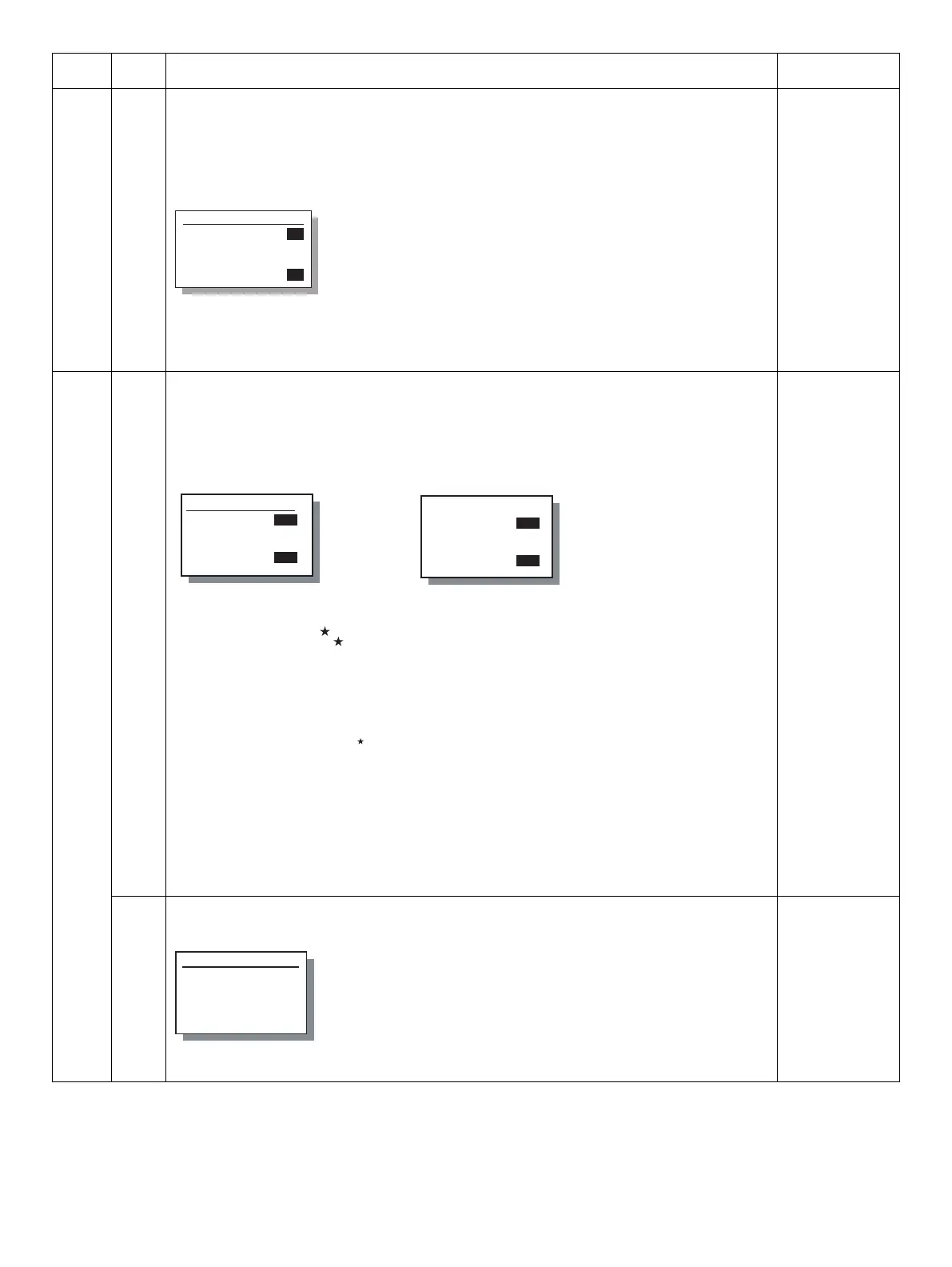
Sim43-13 PICK INTVL
1:PICK INTVL
[ 0-1]
0
0
Code: Setting
0: Disable (Default)
1: Enable
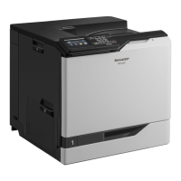
Sim44-1 TONER CONT
1:COV
2:LIFE
3:DRIP
1/2 [ 0- 1]
0
0
0
0
Sim44-1 TONER CONT
4:BETA
5:UNCONDITIONAL
2/2 [ 0- 1]
0
0
0
0
Display mode : Setting mode Display : Setting
COV
LIFE
DRIP
BETA
UNCONDITIONAL
: Print ratio correction
: Life correction
: Drip supply
: Purge process
: Unconditional toner supply
0 : Disable
1 : Enable
Name
TONER DEN_LT
TONER DEN_ST
:Display content
:Current ATC sensor value
:ATC reference value with life correction
quantity added
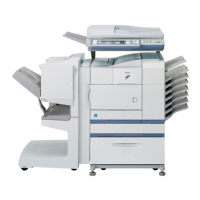
Sim44-16 TONER DISP
1:TONER DEN_LT
nnn
2:TONER DEN_ST
nnn