Appendix&A:&11-Pin&Interface&
!
Signals&and&Pin-Out&
On the left side of the PC-G850V(S) there is an 11-pin interface intended for
communication with other devices. It is a multi-functional interface, hence it can operate
in different (sub-)modes. The actual mode is selected through operational commands or
menue items of the PC-G850V(S).
1. SIO / RS-232C-mode (e.g. OPEN“COM:“)
2. SSIO-mode (Synchronous Serial Input/Output)
a. CE-126P print protocol (e.g. LPRINT without preceding OPEN)
b. LPRT-protocol (e.g. OPEN“LPRT:“)
3. PWM-mode (Pulse Width Modulation)
a. CE-126P tape protocol (e.g. BSAVE/BLOAD with a CE-126P)
b. Generic PWM-protocol (e.g. BSAVE/BLOAD with another PC-G850V)
4. PIO-mode (e.g. OPEN“PIO:“)
Programmable, 8-bit parallel port interface
5. PIC-mode (activated by the PIC-loader in the assembler menue)
Programming interface for PIC microcontrollers
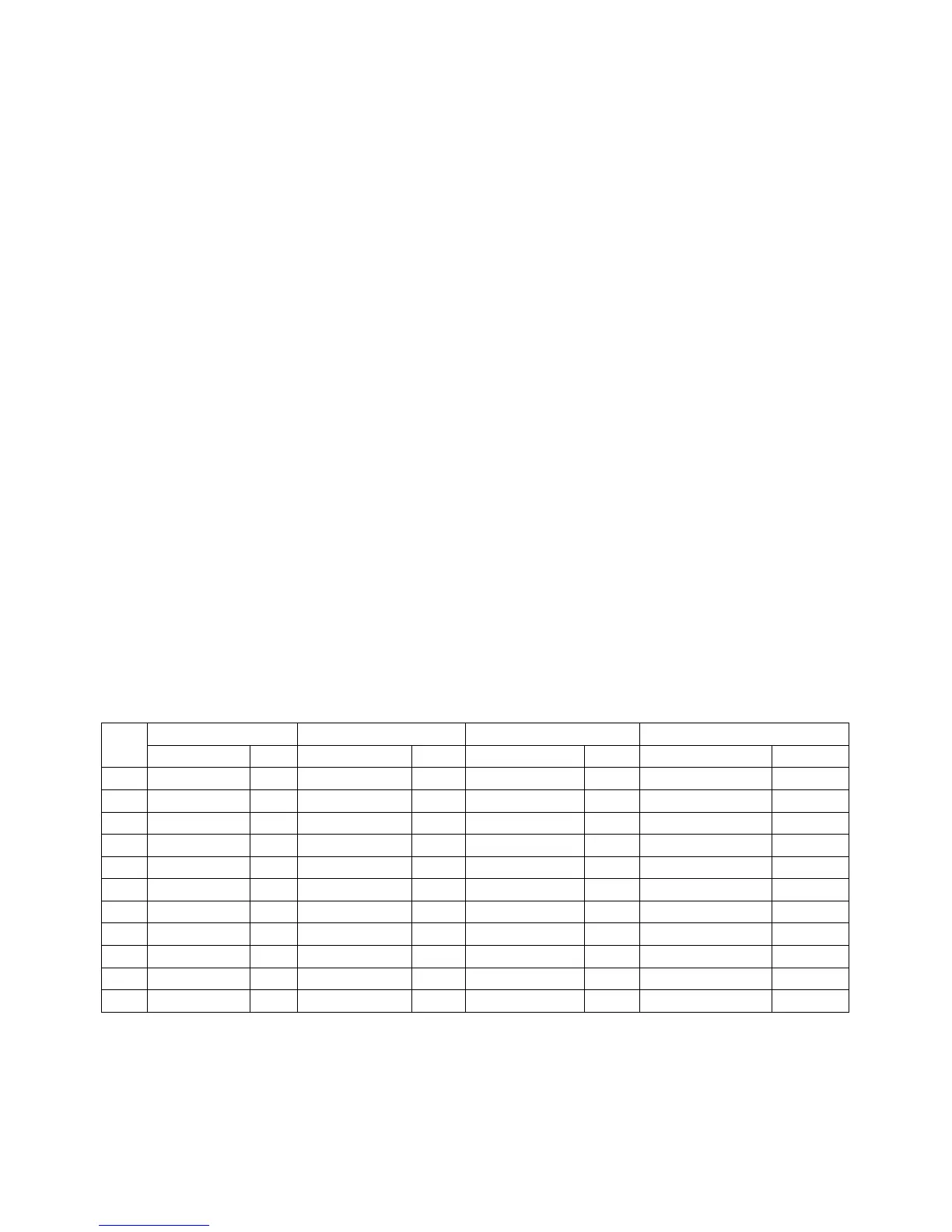
The association of physical pins to logical signals (called pin-out) as well as the
configured direction for input (I) or output (O) depends on the active mode. The following
table gives an overview. Looking from the left side of the PC-G850V(S) pin-1 is the
leftmost and pin-11 the rightmost.