Comments on the code:
• Line 4: Bit-mask for bit-1 (0b00000010), i.e. push button input
• Line 6: Global state variable for the push button
• Line 7: Global state variable for the LED
• Line 11: The interface is opened in PIO-mode for read and write.
• Line 15: Configure bit-1 / pin-5 as input. All other signals are outputs.
• Line 20: This function detects the transition from bit-1 = 0 to bit-1 = 1, i.e. the close
event of the push button.
• Line 23: The PIO-port is read and all bits are masked out, except bit-1.
• Line 30: This function changes the state of the LED.
• Line 33: The new LED-state (bit-0) is written to the port.
Unused outputs are set to 0.
• Line 104: Main-loop, abort by ON/BREAK-key.
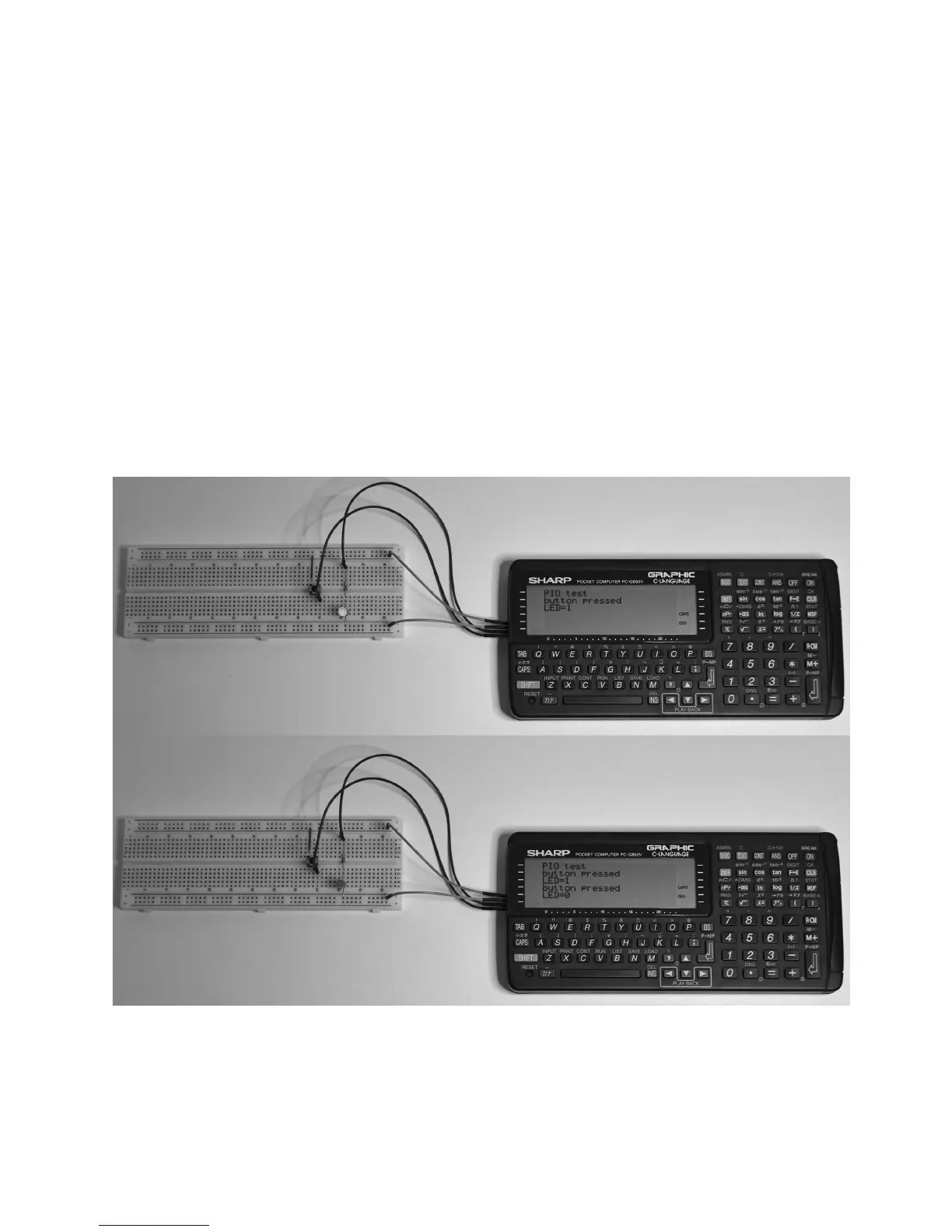
The following images show an experimental setup and the respective trace outputs on
the display of the PC-G850V.