EasyManuals Logo

Sharp PC-G850VS User Manual

Sharp PC-G850VS
22 pages
To Next Page IconTo Next Page
To Previous Page IconTo Previous Page
Page #12 background imageLoading...
Page #12 background image
SHARP&PC-G850V(S)&&&User&Manual&-&&Appendix!A:!11-Pin!Interface&
!
12!
The signal semantics of the LPRT-protocol is as follows:
Pin
#
Signal
Direction
Semantics
4
BUSY
Out
Frame-indicator for each transmitted byte
5
DOUT
Out
Data line
7
XOUT
Out
Clock pulse with pause after each byte
9
ACK
In
LOW: Receiver ready
HIGH: PC-G850V(S) must wait
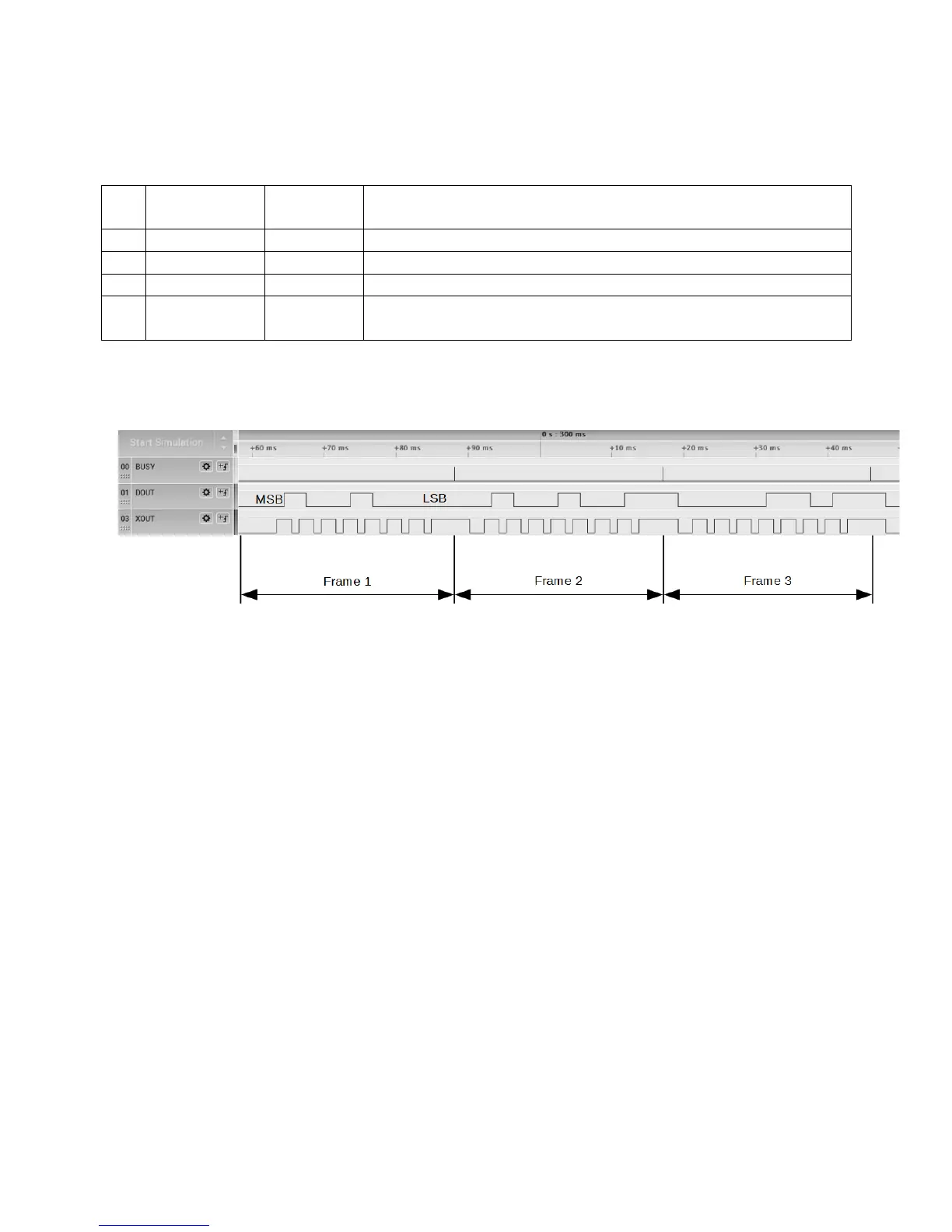
The next diagram shows the signal timings:
Data is transferred byte-wise with MSB-first. DOUT is valid at the rising edge of the clock
pulse. The BUSY-signal provides an additional reference frame for each byte.
PWM-Mode:&CE-126P&Tape&Protocol&
!
This protocol is activated by the commands BSAVE, BSAVEM, BLOAD, BLOADM,
BLOAD? when a CE-126P (or compatible cassette interface) is attached in order to store,
load or verify BASIC programs or binary data sections (e.g. machine language programs)
to / from a tape recorder like the CE-152.
The protocol includes the SSIO-handshake of the CE-126P printer protocol but the actual
data transfer is realized via pulse width modulation (the digital equivalent of analog
waveforms). So it’s a kind of mixed SSIO/PWM-protocol.

Questions and Answers:

Question and Answer IconNeed help?

Do you have a question about the Sharp PC-G850VS and is the answer not in the manual?

Sharp PC-G850VS Specifications

General IconGeneral
BrandSharp
ModelPC-G850VS
CategoryPDA
LanguageEnglish

Related product manuals