R-231NW
6 - 3
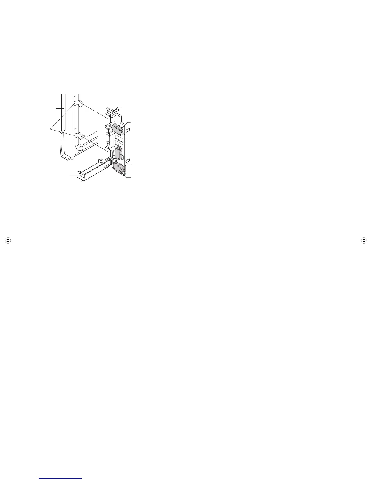
1. DOOR OPEN MECHANISM
The door is opened by pushing the open button on the control
panel, refer to the Figure D-1.
When the open button is pushed, the open button pushes up
the switch lever, and then the switch lever pushes up the latch
head. The latch heads are moved upward and released from
latch hook. Now the door will open.
[3] DESCRIPTION AND FUNCTION OF COMPONENTS
2. DOOR SENSING AND SECONDARY
INTERLOCK SWITCHES
The secondary interlock switch is mounted in the lower position
of the latch hook and the door sensing switch in the primary
interlock system is mounted in the upper position of the latch
hook. They are activated by the latch heads on the door. When
the door is opened, the switches interrupt the power to all high
voltage components. A cook cycle cannot take place until the
door is fi rmly closed thereby activating both interlock switches.
The primary interlock system consists of the door sensing switch
and primary interlock relay located on the control circuit board.
3. MONITOR SWITCH
The monitor switch is activated (the contacts opened) by the
latch head on the door while the door is closed. The switch is
intended to render the oven inoperative, by means of blowing
the monitor fuse, when the contacts of the primary interlock relay
(RY2) and secondary interlock switch fail to open when the door
is opened.
Functions:
1) When the door is opened, the monitor switch contacts close
(to the ON condition) due to their being normally closed.
At this time the primary interlock relay (RY2) and secondary
interlock switch are in the OFF condition (contacts open)
due to its being normally open contact switches.
2) As the door goes to a closed position, the monitor switch
contacts are fi rst opened and then the door sensing switch
and secondary interlock switch contacts close.
3) If the door is opened, and the primary interlock relay (RY2)
and the secondary interlock switch contact fail to open, the
monitor fuse blows simultaneously with closing of the
monitor switch contacts.
CAUTION: BEFORE REPLACING A BLOWN MONITOR FUSE,
TEST THE DOOR SENSING SWITCH, PRIMARY INTERLOCK
RELAY (RY2), SECONDARY INTERLOCK SWITCH AND
MONITOR SWITCH FOR PROPER OPERATION. (REFER
TO CHAPTER “TEST PROCEDURE”).
NOTE: MONITOR FUSE AND MONITOR SWITCH ARE
REPLACED AS AN ASSEMBLY.
Figure D-1. Door Open Mechanism.
Latch
Heads
Door
Switch Lever
Latch Hook
Monitor Switch
Door Sensing
Switch
Secondary
Interlock Switch
4. TURNTABLE MOTOR
The turntable motor rotates the turntable located on the bottom
of the oven cavity, so that the food on the turntable is cooked
evenly. The turntable may turn in either direction.
5. COOLING FAN MOTOR
The cooling fan motor drives a blade which draws external cool
air. This cool air is directed through the air vents surrounding
the magnetron and cools the magnetron. This air is channelled
through the oven cavity to remove steam and vapours given
off from the heating foods. It is then exhausted through the
exhausting air vents at the oven cavity.
6. TEMPERATURE FUSE (OVEN)
The temperature fuse, located on the top of the oven cavity, is
designed to prevent damage to the oven by fi re. If the food load
is overcooked, by either error in cook time or defect in the control
unit, the temperature fuse will open.
Under normal operation, the temperature fuse remains closed.
However, when abnormally high temperatures are reached within
the oven cavity, the temperature fuse will open at 302°F(150°C),
causing the oven to shut down.
7. THERMAL CUT-OUT (OVEN)
The thermal cut-out, located on the top of the oven cavity, is
designed to prevent damage to the oven by fi re. If the food load
is overcooked, by either error in cook time or defect in the control
unit, the thermal cutout will open.
Under normal operation, the oven thermal cut-out remains
closed. However, when abnormally high temperatures are
reached within the oven cavity, the oven thermal cut-out will open
at 293°F(145°C), causing the oven to shut down.
8. MONITOR FUSE
1) The monitor fuse blows when the contacts (COM-NO) of the
primary interlock relay (RY2) and the secondary interlock
switch remain closed with the oven door open and when the
monitor switch closes.
2) If the wire harness or electrical components are short-
circuited, this monitor fuse blows to prevent an electric
shock or fi re hazard.
9. NOISE FILER
The noise fi lter prevents the radio frequency interference that
might fl ow back in the power circuit.
Service_R-231NW.indd 12Service_R-231NW.indd 12 6/24/09 3:56:42 PM6/24/09 3:56:42 PM