R-231NW
11 - 5
2. INSTALLATION
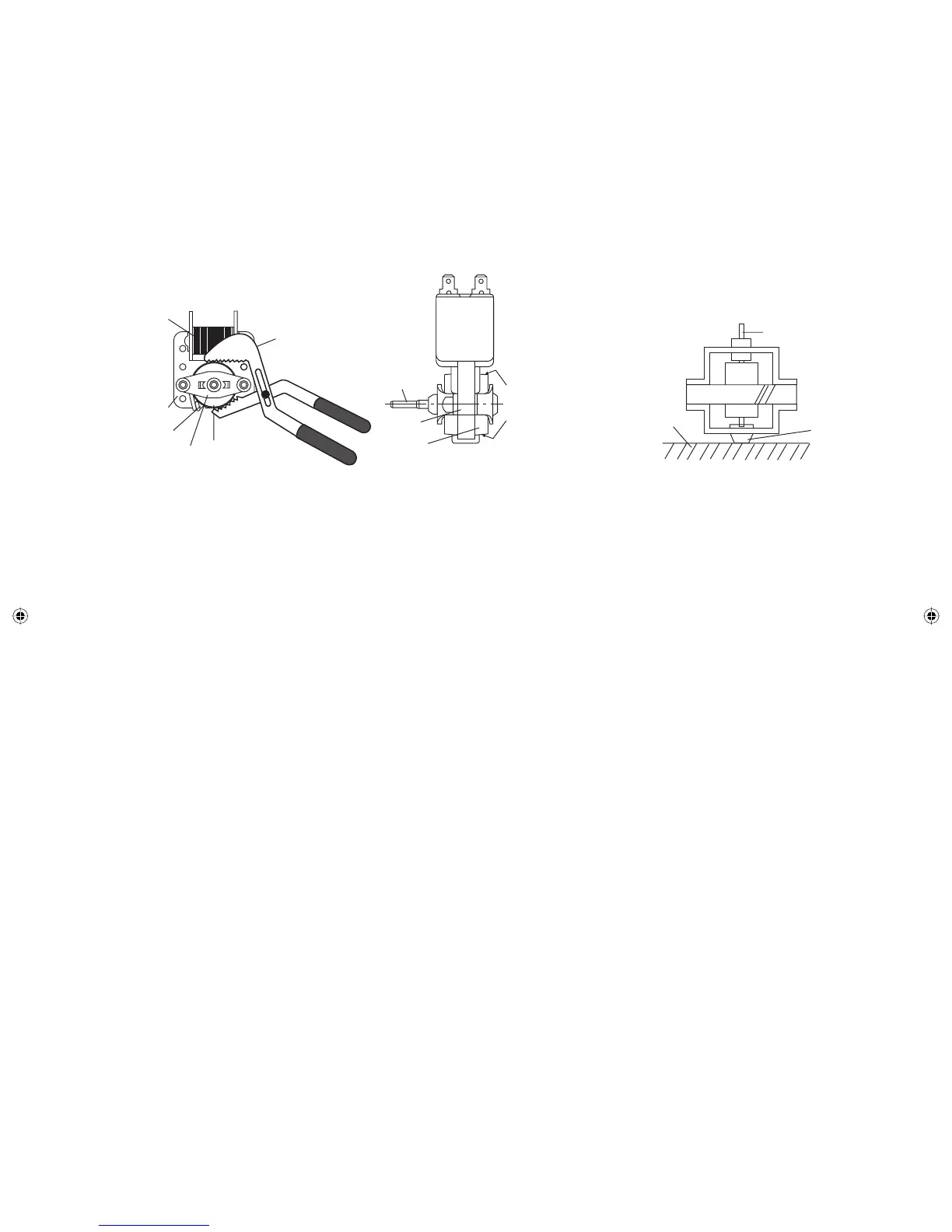
1. Install the fan blade to the fan motor shaft according to the
following procedure.
2. Hold the center of the bracket which supports the shaft of
the fan motor on the fl at table.
3. Apply the screw lock tight into the hole (for shaft) of the fan
blade.
4. Install the fan blade to the shaft of fan motor by pushing the
fan blade with a small, light weight, ball peen hammer or
rubber mallet.
1. REMOVAL
1. Disconnect the power supply cord and remove outer case.
2. Open the door and block it open.
3. Discharge high voltage capacitor.
4. Remove the control panel assembly, referring to section of
CONTROL PANEL ASSEMBLY REMOVAL.
5. Remove the switch lever from the oven cavity.
6. Disconnect wire leads from the switches.
7. Remove two (2) screws holding latch hook to oven fl ange.
8. Remove latch hook assembly from oven fl ange.
9. Push outward on the two (2) retaining tabs holding switch in
place.
10. Switch is now free.
Gap
Rotor
Bracket
Stator
Groove joint pliers
Coil
Shaft
Axis
Stator
Rotor
These are the positions
that should be pinched
with pliers.
Shaft
Table
Center of
bracket
Rear View
Side View
[12] DOOR SENSING SWITCH/SECONDARY INTERLOCK SWITCH AND MONITOR SWITCH REMOVAL
2. REINSTALL
1. Re-install each switch in its place. The secondary interlock/
monitor switches are in the lower position and the door
sensing switch is in the upper position.
2. Secure latch hook (with two (2) mounting screws) to oven
fl ange.
3. Re-connect wire leads to each switch. Refer to pictorial
diagram.
4. Install the switch lever to the oven cavity.
5. Reinstall the control panel assembly to the oven cavity.
6. Reconnect wire leads to the control unity, referring to the
pictorial diagram.
7. Make sure that the monitor switch is operating properly and
check continuity of the monitor circuit. Refer to chapter “Test
Procedure” and Adjustment procedure.
[13] DOOR SENSING SWITCH/SECONDARY INTERLOCK SWITCH AND MONITOR SWITCH
ADJUSTMENT
1. Adjustment
1. Disconnect the power supply cord, and then remove
outer case.
2. Open the door and block it open.
3. Discharge high voltage capacitor.
If the door sensing switch, secondary interlock switch
and monitor switch do not operate properly due to a
misadjustment, the following adjustment should be
made.
4. Loosen the two (2) screws holding latch hook to the
oven cavity front fl ange.
5. With door closed, adjust latch hook by moving it back
and forth, and up and down. In and out play of the
door allowed by the upper and lower position of the
latch hook should be less than 0.5mm.
The vertical position of the latch hook should be
adjusted so that the door sensing switch and
secondary interlock switch are activated with the door
closed. The horizontal position of the latch hook
should be adjusted so that the plunger of the monitor
switch is pressed with the door closed.
6. Secure the screws with washers fi rmly.
7. Check the operation of all switches. If each switch has
not activated with the door closed, loosen screw and
adjust the latch hook position.
CAUTION: DO NOT HIT THE FAN BLADE STRONGLY WHEN
INSTALLED BECAUSE THE BRACKET MAY BE
TRANSFORMED.
MAKE SURE THAT THE FAN BLADE ROTATES
SMOOTH AFTER INSTALLED.
MAKE SURE THAT THE AXIS OF THE SHAFT IS
NOT SLANTED.
5. Install the fan motor assembly to the oven cavity back plate
with two (2) screws.
6. Connect the wire leads to the magnetron and fan motor,
referring to the pictorial diagram.
Service_R-231NW.indd 29Service_R-231NW.indd 29 6/24/09 3:56:49 PM6/24/09 3:56:49 PM