R-231NW
11 - 2
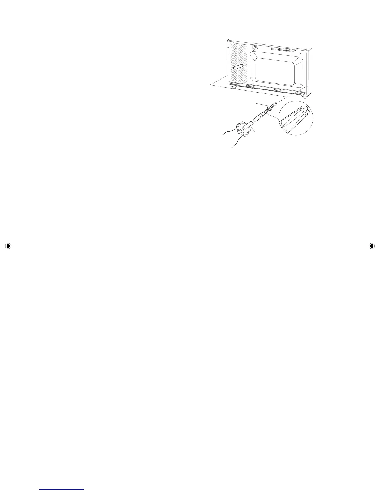
[2] OUTER CASE REMOVAL
To remove the outer case, procedure as follows.
1. Disconnect the power supply cord.
2. Open the oven door and block it open.
3. Remove the two (2) screws from the lower portion of the
rear cabinet using a T20H Torx type or GTXH20-100 screw
driver.
4. Remove the remaining three (3) screws from the upper
portion of the rear and two (2) screws along the right side of
outer case.
5. Slide the entire outer case back out about 1 inch (3 cm) to
free it from retaining clips on the cavity face plate.
6. Lift entire outer case from the unit.
CAUTION: DISCONNECT OVEN FROM POWER SUPPLY
BEFORE REMOVING OUTER CASE.
DISCHARGE THE HIGH VOLTAGE CAPACITOR
BEFORE TOUCHING ANY OVEN COMPONENTS
OR WIRING.
NOTE: When replacing the outer case, the 2 special Torx
screws must be reinstalled in the same locations.
[3] MAGNETRON REMOVAL
1. Disconnect the power supply cord and remove outer case.
2. Open the oven door and block it open.
3. Discharge high voltage capacitor.
4. Remove the two (2) screws holding the air duct to the oven
cavity.
5. Release the air duct from the oven cavity.
6. Disconnect the wire leads from magnetron.
[4] HIGH VOLTAGE COMPONENTS REMOVAL
(HIGH VOLTAGE CAPACITOR AND HIGH VOLTAGE RECTIFIER ASSEMBLY)
To remove the components, proceed as follows.
1. Disconnect the power supply cord and remove outer case.
2. Open the oven door and block it open.
3. Discharge high voltage capacitor.
4. Disconnect the high voltage wire (white) of the power
transforme from high voltage capacitor.
5. Disconnect the H.V. wire of the H.V. rectifi er assembly from
the magnetron.
6. Disconnect the fi lament lead (red) of the power transformer
from the H.V. capacitor.
7. Remove one (1) screw holding capacitor holder to bottom
plate.
8. Remove one (1) screw holding ground side terminal of high
voltage rectifi er assembly, and remove capacitor holder.
9. Disconnect the terminal of high voltage rectifier assembly
from high voltage capacitor.
10. Now the H.V. rectifi er assembly and H.V. capacitor should
be free.
CAUTION: WHEN REPLACING HIGH VOLTAGE RECTIFIER
ASSEMBLY, ENSURE THAT THE CATHODE
(GROUND) CONNECTION IS SECURELY
FIXED TO THE CAPACITOR HOLDER WITH A
GROUNDING SCREW.
CAUTION: DO NOT REPLACE ONLY HIGH VOLTAGE
RECTIFIER. WHEN REPLACING IT, REPLACE
HIGH VOLTAGE RECTIFIER ASSEMBLY.
1. REMOVAL
1. Disconnect the power supply cord and remove outer
case.
2. Open the oven door and block it open.
3. Discharge high voltage capacitor.
4. Disconnect the wire leads (main wire harness) from
power transformer.
5. Disconnect the filament lead (red) of the power
transformer from magnetron.
6. Disconnect the leads of the power transformer from
high voltage capacitor.
7. Remove the four (4) screws holding the transformer to
bottom plate from the upper side and bottom side.
8. Remove the transformer.
9. Now the power transformer is free.
2. REINSTALL
1. Rest transformer on the bottom plate with its primary
terminals toward the oven face plate.
2. Secure transformer with four (4) screws to the bottom
plate (two screws from upper side and two screws
from bottom side).
3. Re-connect wire leads (primary and high voltage) and
filament leads to the power transformer, magnetron
and high voltage capacitor, referring to “Pictorial
Diagram”.
4. Re-install outer case and check that the oven is
operating properly.
7. Remove the four (4) screws holding the magnetron to the
waveguide.
8. Remove the magnetron from waveguide.
9. Now, the magnetron is free.
CAUTION: WHEN REPLACING THE MAGNETRON, BE
SURE THE R.F. GASKET IS IN PLACE AND
THE MAGNETRON MOUNTING SCREWS ARE
TIGHTENED SECURELY.
[5] POWER TRANSFORMER REMOVAL
Special screw
Screw Driver
(Type: TORX T20 H or
GTXH20-100)
Service_R-231NW.indd 26Service_R-231NW.indd 26 6/24/09 3:56:47 PM6/24/09 3:56:47 PM