R-3A53
R-3A53B
TEST PROCEDURES (CONT’D)
PROCEDURE
LETTER COMPONENT TEST
TOUCH CONTROL PANEL ASSEMBLY TEST
The touch control panel consists of circuits including semiconductors such as LSI, I&, etc.
Therefore, unlike conventional microwave ovens, proper maintenance cannot be performed with
only a voltmeter and ohmmeter.
vided into two units, Control
In this service manual, the touch control panel assembly is di-
Unit and Key Unit, and troubleshooting by unit replacement is de-
scribed according to the symptoms indicated.
1. Key Unit.
The following symptoms indicate a defective key unit. Replace the key unit.
a) When touching the pads, a certain pad produces no signal at all.
b) When touching a number pad, two figures or more are displayed.
.
c) When touching-the pads, sometimes a pad produces no signal.
2. Control Unit
The following symptoms indicate a defective control unit. Replace the control unit.
2-l In connection with pads.
a) When touching the pads, a certain group of pads do not produce a signal.
b) When touching the pads, no pads produce a signal.
2-2 In connection with indicators
a) At a certain digit, all or some segments do not light up.
b) At a certain digit, brightness is low.
c) Only one indicator does not light.
d) The corresponding segments of all digits do not light up; or they continue to light up.
e) Wrong figure appears.
f) A certain group of indicators do not light up.
g) The figure of all digits flicker.
2-3 Other possible troubles caused by defective control unit.
a)
Buzzer does not sound or continues to sound.
b) Clock does not operate properly.
c) Cooking is not possible.
d) Proper temperature measurement is not obtained.
M PROCEDURES TO BE TAKEN WHEN THE FOIL PATTERN ON THE PRINTED WIRING
BOARD (PWB) IS OPEN.
To protect the electronic circuits, this model is provided with a fine foil pattern added to the
primary on the PWB, this foil pattern acts as a fuse. If the foil pattern is open, follow the trou-
bleshooting guide given below for repair.
Problem: POWER ON, indicator does not light up.
STEPS OCCURANCE CAUSE OR CORRECTION
1 ‘The rated AC voltage is not present at POWER ter- Check supply voltage and oven power cord. Please
minal of CPU connector (CN-A)
use term “Low voltage transformer” when refering to
transformer Tl
r
2 The rated AC voltage is present at primary side of low Low voltage transformer or secondary circuit defec-
voltage transformer. tive. Check and repair.
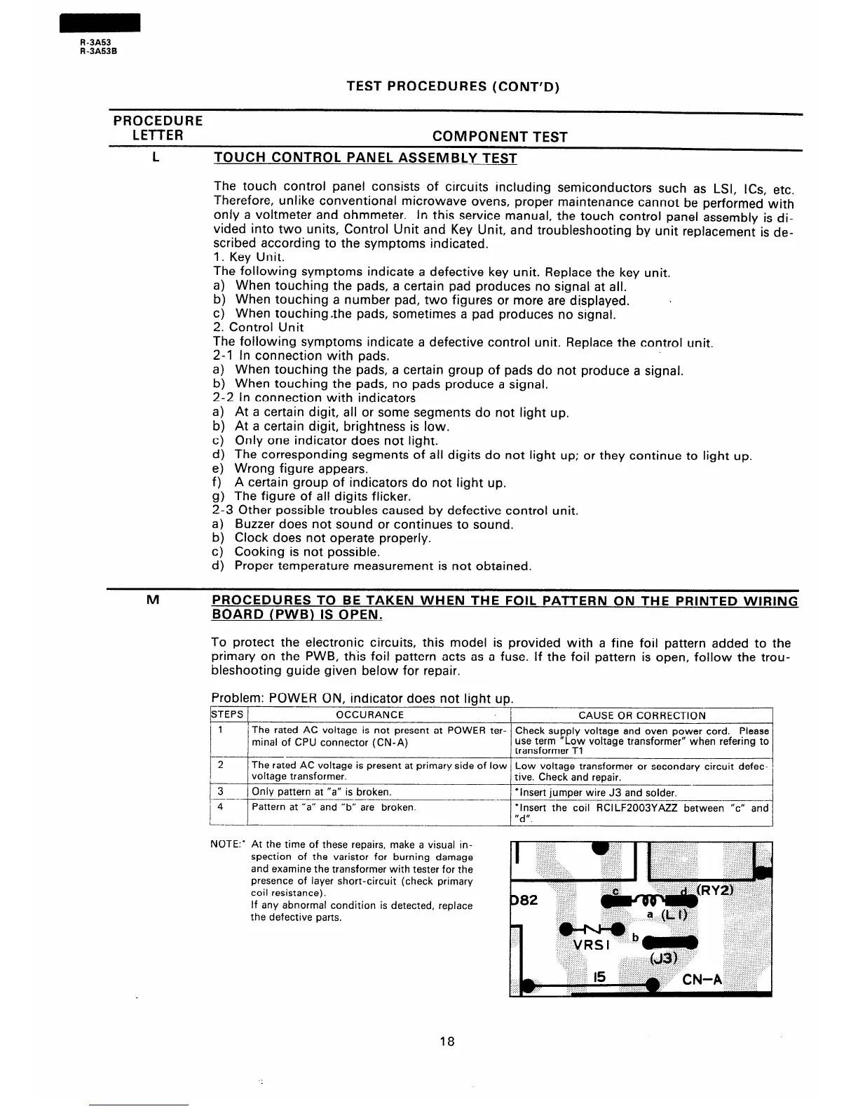
3 Only pattern at “a” is broken.
‘Insert jumper wire J3 and solder.
-
--
4 Pattern at “a” and “b” are broken. *Insert the coil RCILF2003YAZZ between “c”
i--
“d”.
NOTE:’ At the time of these repairs, make a visual in-
spection of the varistor for burning damage
and examine the transformer with tester for the
presence of layer short-circuit (check primary
coil resistance).
If any abnormal condition is detected, replace
the defective parts.
I
D82
I
18