R -3A53
R-3A53B
MAGNETRON REMOVAL
I, CARRY OUT 3D CHECKS
4. Remove the magnetron from the waveguide with
2. Disconnect leads from magnetron.
3. Carefully remove four (4) screws holding
magnetron to waveguide, when removing the
screws hold the magnetron to prevent it from fall-
ing.
care so the magnetron antenna is not hit by any
metal object around the antenna
CAUTION: WHEN REPLACING THE MAGNETRON,
BE SURE THE R.F. GASKET IS IN
PLACE
AND THE
MAGNETRON
MOUNTING SCREWS ARE TIGHTENED
SECURELY.
CONTROL PANEL REPLACEMENT
Removal
1. CARRY OUT 3D CHECKS.
2. Disconnect the leads from the control panel.
3. Raise the tab of the oven cavity.
4. Lift up the control panel assembly.
5. Release the control panel from the oven cavity.
6. Now, the control panel assembly is free.
Installation
1. Put the tabs of the control panel into the holes of
the oven cavity.
2. Push down the control panel.
3. Fold the tab of the oven cavity as shown in Figure
C-4 (a).
Note: If the tab of the oven cavity has been broken,
to hold the control panel to the oven cavity use
the single (1) screw (XOTSD40P12000) as
shown in Figure C-4 (b).
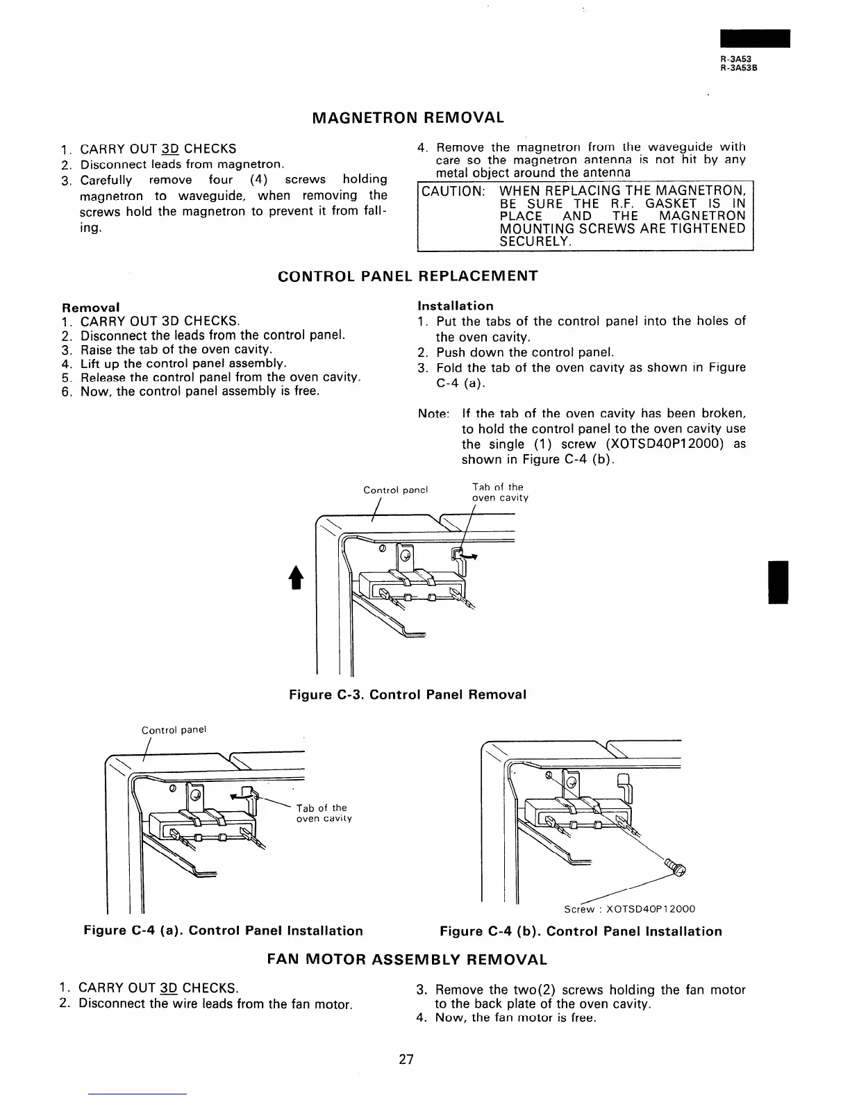
Control panel Control panel
Tab of the
Tab of the
I
oven cavity
ity
Note: If the tab of the oven cavity has been broken,
to hold the control panel to the oven cavity use
the single (1) screw (XOTSD40P12000) as
shown in Figure C-4 (b).
Figure C-3. Control Panel Removal
Control panel
Screw : XOTSD40P 12000
Figure C-4 (a). Control Panel Installation
Figure C-4 (b). Control Panel Installation
FAN MOTOR ASSEMBLY REMOVAL
1. CARRY OUT 3D CHECKS.
2. Disconnect the wire leads from the fan motor.
3. Remove the two(2) screws holding the fan motor
to the back plate of the oven cavity.
4. Now, the fan motor is free.
27