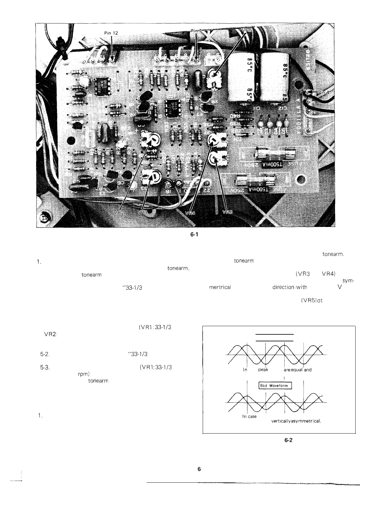
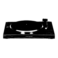
Figure
6-1
ROTATIONAL SPEED ADJUSTMENT OF TURNTABLE
DRIVE MOTOR
I.
Set the power switch to “ON” position.
2. Push the cue/pause control button to raise the
tonearm,
and swing the
tonearm
from its rest to a position over the
outer edge of record by hand.
3. Switch the speed selector to
“33-l/3
rpm” or “45 rpm”
position. A correct speed is achieved when dots in the
stroboscopic viewer become apparently motionless.
4. If dots are moving, in either direction, adjust the fine speed
control until dots appear motionless.
5. If the fine speed control is still insufficient for the adjust-
ment, use the semi-variable resistor
(VRI:
33-l/3
rpm or
VR2:
45 rpm) on the motor drive circuit board as follows:
5-l. Set the fine speed control to “mechanical center”
position.
5-2. Switch the speed selector to
“33-l/3
rpm” of “45 rpm”
position.
5-3. Adjust the semi-variable resistor
(VRI
:
33-l/3
rpm or
VR2: 45
rpm)
until dots appear motionless.
6. Finally return the
tonearm
to its rest manually, or push the
cut-out button.
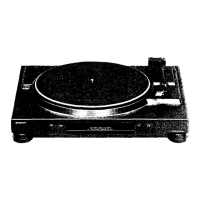
ADJUSTMENT OF
TURNTABLE
DRIVE
MOTOR
DRIVE CIRCUIT
1.
If wow and flutter effect of the turntable drive motor is
inferior to the specified value, correct it in the following
way.
2. Connect the inputs of a dual-beam synchroscope between
pins 4 (earth side) and 7 , and between pins 4 (earth
side) and 12
6. Adiust the semi-variable resistor
IVR5)
ot
that output
waveforms at pins 7 and 12 will be the same in size.
Good Waveform
In’
case
peak values
are
equal’and
wave forms are vertically symmetrical.
I
I
In’case peak values ‘are different and
wave forms are
vertically
asymmetrical.
3. Set the power switch to “ON” position.
4. Push the cue/pause control button to raise the
tonearm.
Bring the
tonearm
from its rest to a position over the outer
edge of record by hand.
5. Adjust the semi-variable resistors
(VR3
and
VR4)
so that
both output waveforms at pins 7 and 12 become
sym-
mertrical
in up and down
direction.with
the value 0
V
as a
center, respectively.
Figure
6-2