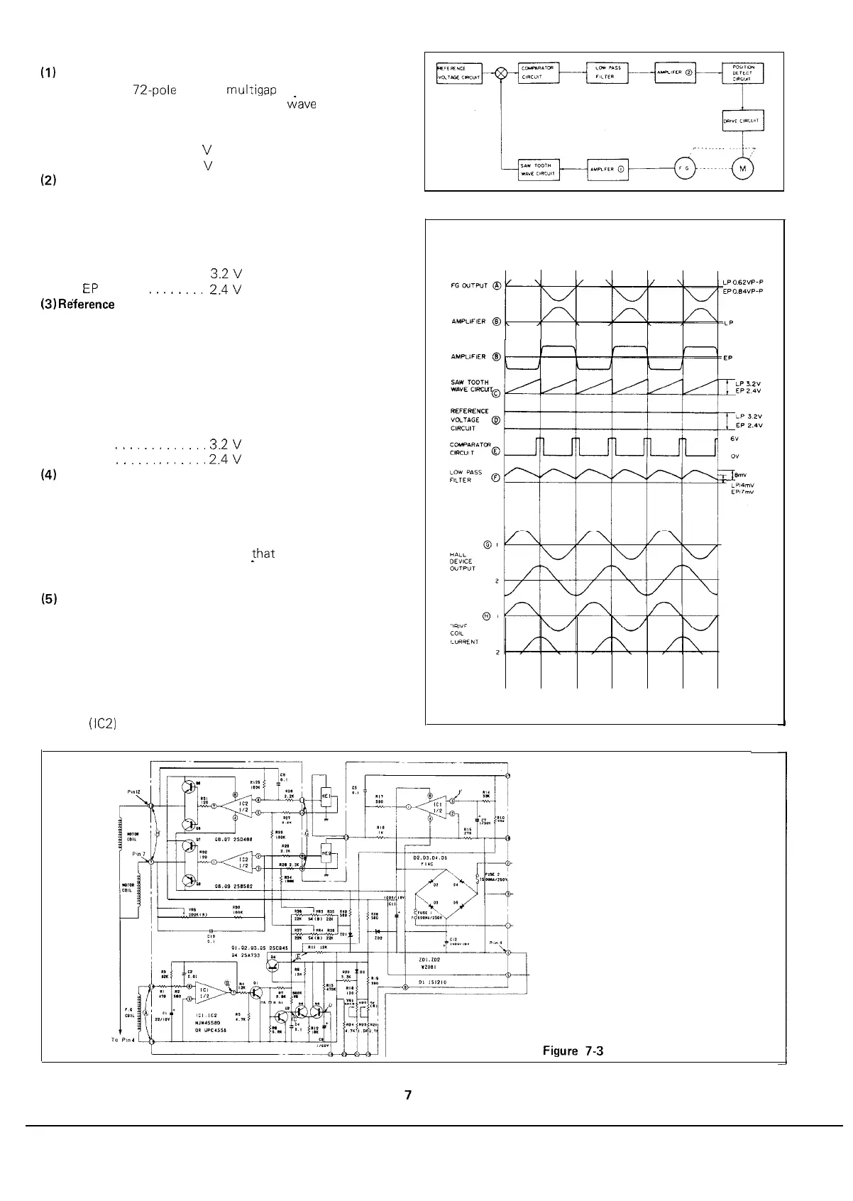
DIRECT DRIVE MOTOR CONTROL CIRCUIT
(I)
Frequency generator
Consists of
72.pole
magnet,
multigap
head having 36 pairs
of yokes, and coils. The 20 Hz sine
wave
is generated
when playing the LP record, and the 27 Hz sine wave
when playing the EP record.
LP 0.62
V
P-P
EP 0.84
V
P-P
(2)
Saw tooth generator circuit
This circuit consists of a charging circuit which comprises
capacitor and resistor and a switching transistor which
discharges in a short time the voltage charged up into the
capacitor. The saw tooth wave is generated having a peak
value that is in proportion to its frequency.
LP
3.2V
EP
__
.__..._.
2.4V
(3)
Re’ference
voltage circuit
Circuit by which the voltage for deciding the rpm of the
motor is obtained; the output of the constant voltage
circuit is fed through a resistance type voltage devider so
that a more constant voltage is acquired.
The circuit is so designed that the divided voltage propor-
tion can be continuously varied by the external variable
resistor (this depends upon the fact of the frequency itself
being made variable in the circuit interior).
LP
.,_._.,_.._..
3.2V
EP
I.....
,.._,..
2.4V
(4)
Comparator circuit
Consists of a differential comparator circuit and a piece of
switching transistor. This circuit compares the peak value
of saw tooth wave with the reference level; when the for-
mer is lower than the latter, this circuit is turned off, and
when higher, it is turned on so
that
the frequency varia-
tion (i.e., rpm variation) is obtained as a variation of the
avarage value of the output pulse.
(5)
Position detector circuit and motor drive circuit
The position detector circuit detects a location of the
rotor magnet by the Hale element, and determines an
order of feeding the current into two drive coil.
The current fed to the Hale element, on the other hand, is
controlled by the low-pars filter, the output voltage of the
Hale element is varied according to the rpm variation, and
that output voltage is amplified by the operational ampli-
fier (IC2) to feed the current to the drive coils.
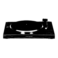
Figure 7-l
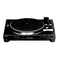
Figure 7-2