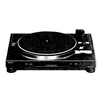
DISASSEMBLY
Caution on Disassembly
Follow the below-mentioned notes when disassembling the
unit and reassembling it, to keep its safety and excellent
performance:
1. Take out a record of the unit.
2. Be sure to remove the input/output plug from the
SM-32H/E
before starting to disassemble the unit.
3. Take off nylon bands or wire holders where they need
be removed when disassembling the unit. After servicing
the unit, be sure to rearrange the leads where they were
before disassembling.
4. Take sufficient care on static electricity of integrated
circuits and other circuits when servicing.
Figure 6-l
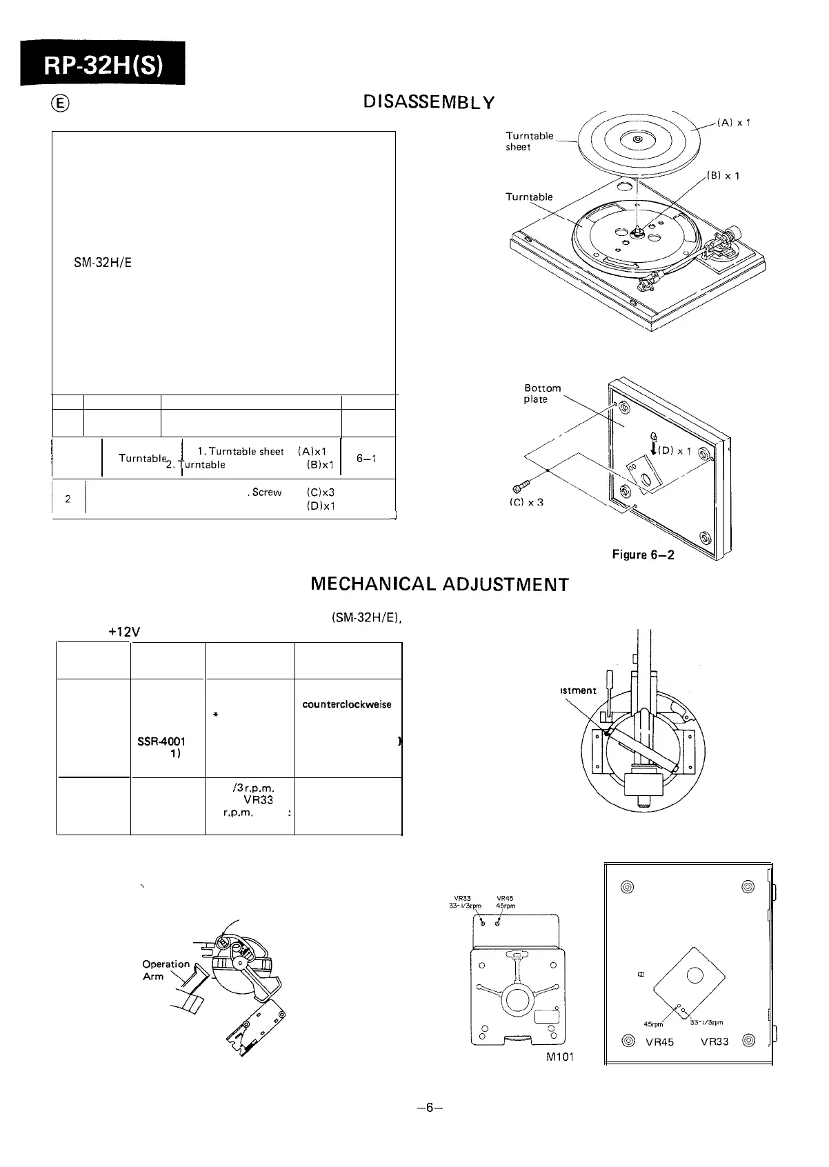
STEP REMOVAL
PROCEDURE FIGURE
1
,
1
Turntab,e
1
l.Turntablesheet
(Alxl
1
6-,
2.Turntable
stopper
(B)xl
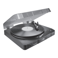
Bottom plate
1 .Screw (C)x3
2. Bottom Plate stopper
(D)xl
6-2
J
MECHAN
I
CAL ADJUSTMENT
TOP VIEW
Connect the Input/output plug to the amplifier
(SM-32H/E),
or supply +12V by an external DC power supply.
REMARKS
ITEM
JIG
Bladed screw
driver
LP record or
Test record
SSR-4001
(SIDE
1)
SSR4002
LP record
which is
provided with
Strobe viewer
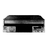
ADJUSTMENT
POINTS
Auto return
adjustment cam
*
See Fig. 6-3,
6-4.
Auto return
Clockwise or
counterclockweise
Auto return count
7-B
(using a test record
Adju
Cam
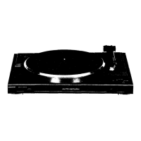
1
33-l
/3
r.p.m.
speed:
VR33
45 r.p.m. speed
:
VFi45
Phono Motor is
kept in rotation,
Phono motor
rotational
speed
Figure 6-4
\
BOTTOM VIEW
,,
Adjustment Cam
PHONO MOTOR
Ml01
Figure 6-3
Figure 6-5
-6-