CARTRIDGE REPLACEMENT
A suitable cartridge has a weight range from
4g
to
6g
and the
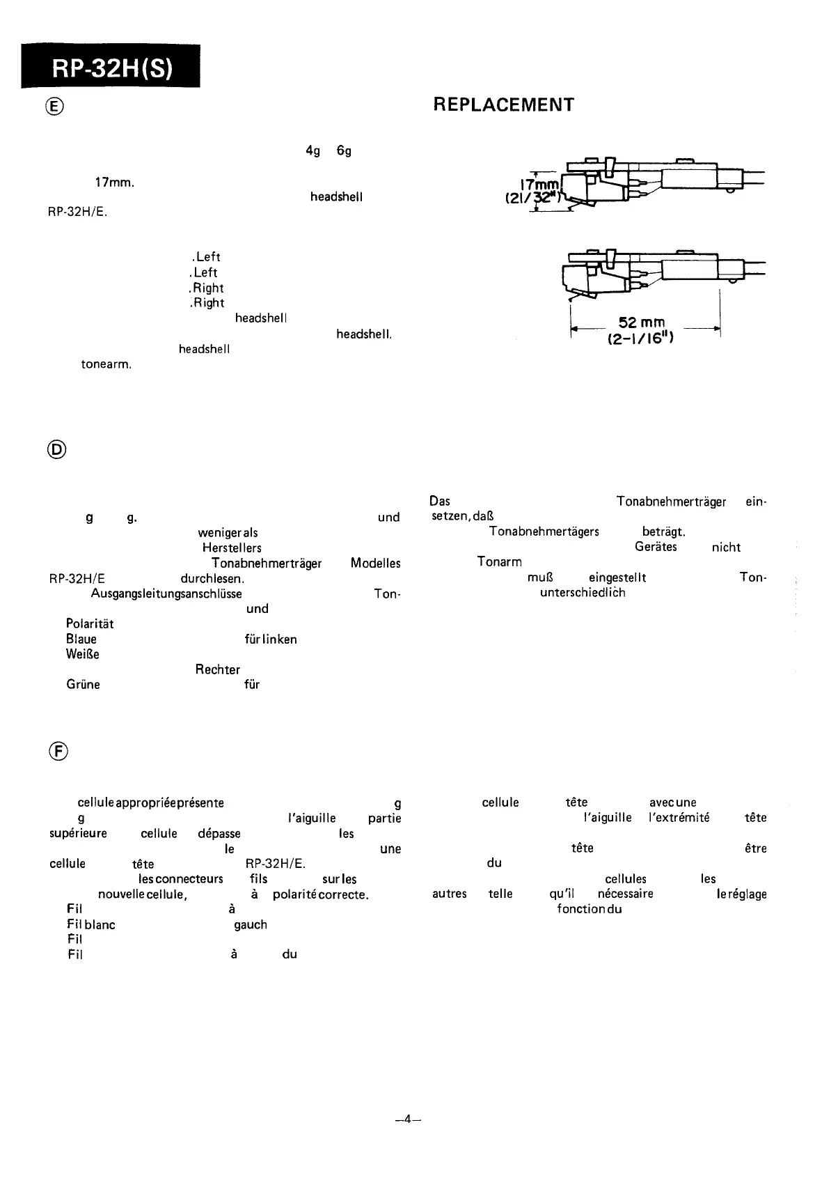
distance from stylus tip to the top of cartridge does not
exceed
17mm.
Read the manufacturer’s fitting instructions
carefully before installing a cartridge into the
headshell
of the
RP-32HlE.
1. Slide the output lead connectors onto the new cartridge
terminals, taking care to observe correct polarity.
Blue lead . . . . . . , . .
.Left
channel Earth
White lead . . . . . , . .
#Left
channel
Red lead . . . . . . . . . *Right channel
Green lead . . . . . , . .
*Right
channel Earth
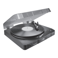
2. Place the cartridge into the
headshell
with a distance of
52mm between the stylus tip and the end of the
headshell.
l
On this unit the
headshell
cannot be removed from the
tonearm.
3. The tracking force will require readjustment because the
cartridge weights differ.
Figure 4-l
AUSWECHSELN DES TONABNEHMERSYSTEMS
Das zu verwendende. Tonabnehmersystem hat ein Gewicht
2.
Das
Tonabnehmersystem in den Tonabnehmertrager so
ein-
von 4
g
bis 6
g.
Der Abstand zwischen der Nadelspitze
und
setzen,
daR
der Abstand zwischen der Nadelspitze und dem
Tonabnehmeroberseite ist
weniger
als
17 mm.
Ende des
Tonabnehmertagers
52 mm betragt.
Die Montagehinweise des Herstellers vor Einsetzen des Ton-
* Der Tonabnehmertrlgers dieses Gerltes kann nicht von
abnehmersystems in den Tonabnehmertrager des
Modelles
dem Tonarm entfernt werden.
RP-32H/E
aufmerksam
durchlesen.
3. Die Auflagekraft
mu6
nueu eingestellt werden, da die Ton-
1. Die
Ausgangsleitungsanschliisse
in die Klemmen des
Ton-
abnehmergewichte unterschiedlich sind.
abnehmersystems einsetzen
und
dabei auf die richtige
Polaritlt
achten.
Blaue
Leitung . . . . .
Erdung
fiir
linken Kanal
Weil3e
Leitung , . . . . Linker Kanal
Rote Leitung . . . . . ,
Rechter
Kanal
Griine Leitung . . . . .
Erdung
fiir
rechten Kanal
REMPLACEMENT DE LA CELLULE
Une cellule
appropriee
presente
une gamme de poids entre 4
g
et 6
g
et la distance entre la pointe de
I’aiguille
et la partie
superieure
de la cellule ne
depasse
pas 17mm. Lire
les
instruc-
tions de montage fournies par
le
fabricant avant d’installer
une
cellule dans la tete de lecture de la
RP-32H/E.
1. Faire glisser
les
connecteurs
des
fils
de sortie
sur
les
bornes
de la nouvelle cellule, en veillant
a
la polarite correcte.
Fil bleu . . . . . . , . . .
Mise
a
la terre du canal gauche
Fil blanc . . . . . . . . . Canal
gauch
Fil rouge . . . . . . . . . Canal droit
Fil vert . . . . . . . . . .
Mise
a
la terre
du
canal droit
2. Placer la cellule dans la
t&e
de lecture
avec
une
distance de
52mm entre la pointe de
I’aiguille
et
I’extremite
de la
t&te
de lecture.
l
Sur cet appareil, la
t&e
de lecture ne peut pas
etre
retiree
du
bras de pick-up.
3. Les poids des ensembles de cellules different
les
uns des
autres
de
telle
sorte
qu’il
est
necessaire
de refaire
le
reglage
de la force d’appui en
fonction
du
pids.
-4-