I
K’”‘
——————.-—-.——
SF-7300
SF-7350
(Tmsion and cam drum normal positionadjustmentsare r-
quiredafter r~lacement or removalof the lensdrtie tire.)
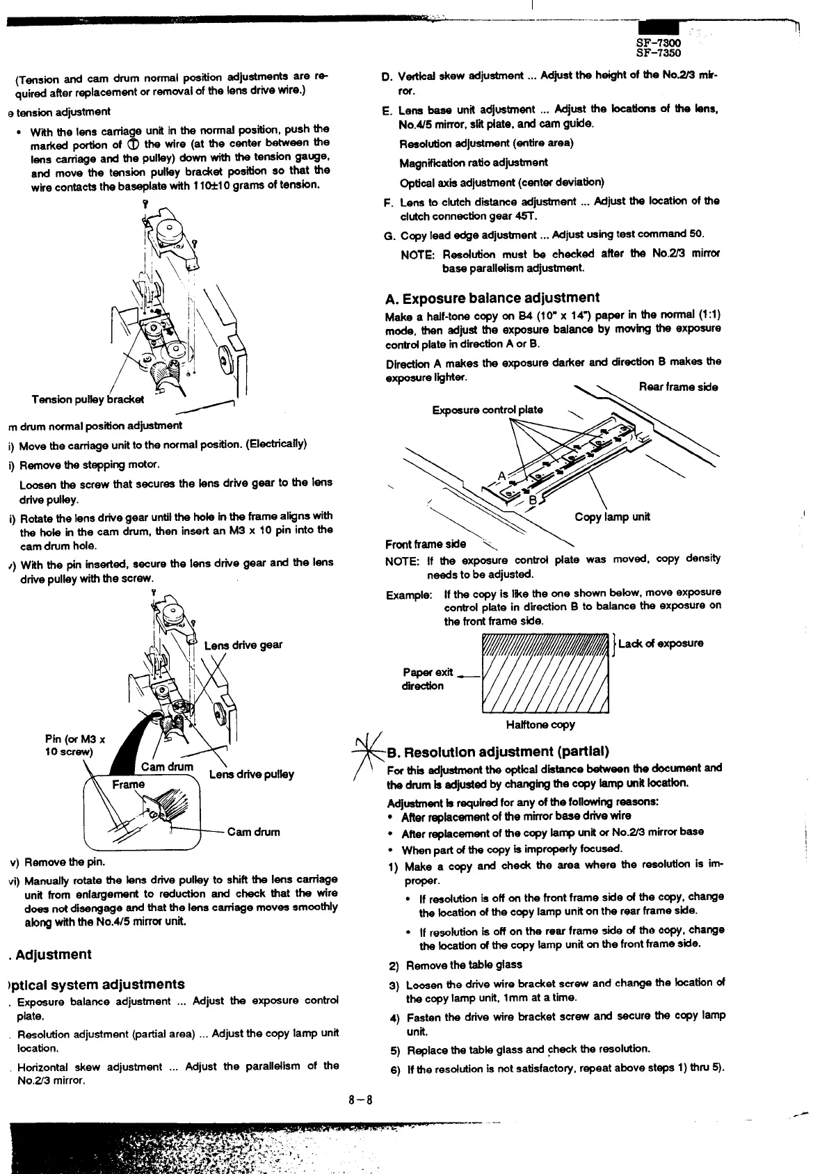
e tensionadjustment
●
With the lens carnage unit in the nond position,push the
marked phn of @ tk tire (at tie c~ter b~een tie
lens carriage and the pulky) down with the tension gauge,
and move the tension pdky bradet position so that the
wirecontactsthe baseplatewith 11M1O grams of tension.
Y-
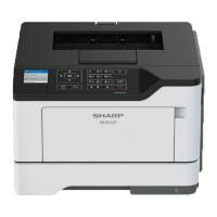
m drumnormalpositionadjustment
i) Move ttre carnage unitto the normalpostion. (Electrically)
i) Removethe steppingmotor.
Loosenthe screw that secures the kms drive gear to tie lens
drivepUlky.
i) Rotatethe lensd~e gear untilthe hok inthe frame alignswith
the hob in the cam drum, then insertan MS x 10 pin into the
cam drumhole.
~) With the pin inserted,secure the lens drive gear and the lens
drivepulleywiththe screw.
Y
L
1
v) Removethe pin.
vi) Manud& rotate the bns drive pulky to shiftthe lens carriage
unit from enlargement to reductionand check that the wire
does notdisengage end that the lenscarriage moves smoothly
ab~ withthe No.W5 mirrwunk.
. Adjustment
)ptlcal system adjustments
. Exposurebalanceadjustment... AdjusttheexposUreCOntr~
plate.
Resolutionadjustment(partialarea)..Adjustthecopylampunit
Iwation.
Horizontal skew adjustment ... Adjust the paralldism of the
No.Z3 mirror.
D.
E.
F.
G.
Vtikd skew adjustment...
Adjustthe heightof tie No= mk-
ror.
Lena base unit adjustment ...
Mjuat the kcatfona of the kns,
No.45 mirror,sri #ate, and cam guide.
Reedution adjustment(entirearea)
Magnifkationratioadjustment
Optbel axisadjustment(centerdeviation)
Lena to clutchdistance adjustment ... Adjustthe locationof the
clutchconnectiongear ~.
Copylead edge adjuatient ... Adjustusi~ test command50.
NOTE: Reeddon must be checked after the No.~ mirror
base paralldiem adjustment.
A. Exposure balance adjustment
Makea half-tonecopyonS4(10”x 147paperinthenorrnd(1:1)
mode,thenadjusttheexposurebdencebymovingtheexposure
conbdplateindirectionAorB.
DirectkAmakestheexposuredarkeranddirectionBmakesthe
exposureI@hter.
Rearframeside
\
~oeuremntrdpkte \
\~p&:
Frontframe side “>
\
NOTE: If the exposure control date was moved, copy density
needsto be adjusted.
Example: If the copyis likethe one shownbebw, move ex~sure
controlpkte in directionB to balance the exposureon
the frontframe side.
1
La& ofexposure
P~ exit —
dir-n
HaHone copy
,,
F
B.Resolutionadjustment(partial)
F- this adjustmentthe optkd dietarrsebetween the documentand
the drumk adjustedby cheng~ the copytip unitbcetbn.
Adjustmentb requiredfor any of the foll~ng reasons:
● Afterrepkcement ofthe mkor base dfie tire
● Afterrepkcement of the copykrnp unitorNo.~ mirrorbaee
● When partd the copyis improper~focu-.
1)
2)
3)
4)
5)
6)
Makea copyandche~ theweawherethereeolutfonisin
proper.
● If reedutionis off on the frontframe side of the copy,change
the &tion of the copy lamp uniton the rear frameside.
* If resolutiti ia off on the rear frame stie d tie copy,change
the -tion of the copyhmp uniton the frontframe side.
Removethe tabb glass
Loosenthe drive wire bracket screw and change the kcabn of
the copylamp unit,lmm at a time.
Fasten the drive wire bracket screw and secure the copy lamp
unit.
Replacethe tabk glass and checkthe resolution.
If the resofdon is notsatisfacto~, repeat above steps1)
thN ~.
,(
8–8