-:~:::,~::.,::,,:{.. ., :’,,
-
W”...-..,*,-! . .
@
(0
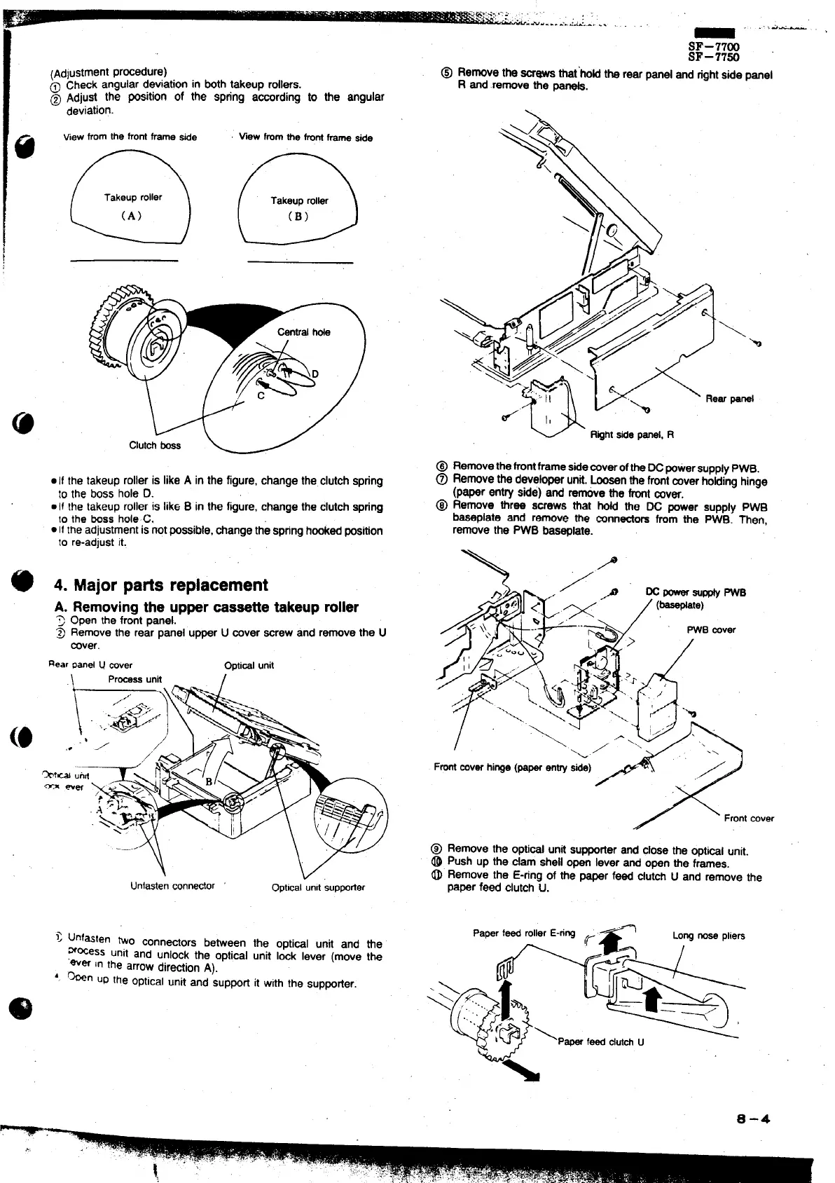
~Adlustmentprwedure)
@ Check angular d8Viationin bothtakeup rollers.
@ Adjust the POSltlOnof the Spflng according to the angular
deviation.
Viewfromthefrontframewe
Vwwfmmthefrontf- side
@ @
.1{ the takeuprolleris likeA in the figure,change the clutchspring
to the boss hole D.
● If the takeuprolleris like B in the figure,changethe clutchspring
10the bossholeC.
. IItheadjustmentisnotpossible,tiange the springhmked position
to re-adjustit.
4. Major patis replacement
A. Removingthe uppercassettetakeuproller
T
Open the frontpanel.
~ Removethe rear panel upperU aver mew and removethe U
rover.
RearPmd u wver
Oprimlunit
\
Prtiss unit
I
Unfastenconneator
Opticalunitsuppofler
> unfasten two conne~ors between the opti~l unit and tie
m~ess unit and unlock the optical unit Id lever (move tk
‘wer in the arrowdirectionA).
‘. ~n UPthe opticalunit and ‘supporfit with the SuppOrter.
_ .-.i-’
SF–77W
SF–77%
@ Removethe=- that’hoti the rearpanel and rightsidepanel
R and removethe -s.
\h
panel
@ Removethefrontframestie~verof~e Wpowersupply PWB.
@ Removethe developerunti,Loosenthefrontmverfroidinghinge
(paper entry side) and
tie the frontcover.
@ Remove three screws that hoti the DC power supply PWB
baseplate and remove me mnntiors from the PWB. ~en,
removethe PWB bas~late.
\
,./
/
\
Frontaver
@ Remove the optiml unti supporterand closethe optial unit.
@ Push up the clam shellopen lever and open the frames.
~“ Remove the E-ringof the paper feed clutd U and remove the
paperfeed clutchu.
‘%
‘ape’‘- ‘“”er‘-”wc
LOWnosepliers
*@*&
-\
0-4
,.,