.. ., ..
-’
B. Exwute test command50
~F~gR)C + P + O + P ~ 5 + 0 + PSW to exwute test
mmmti 50. As the ready lamp turnson, the wrrent mumber
between1and99 isdisdayedto showtheatentsof ~C-a.
@ Press Otwo times (00 displayed)and the PSW key to resetthe
PSC-a. At the same time a apy is made, the @ntentsof P=-a
is reset to 00.
@ Press the PAUSE key. ~e’pause lamp turnson.
The fgure preset (O-w) is displayedto show the oontentsof
PSC-b.
@ Press O twice (00 displayed) and the PSW key to reset the
PSC-b. At the same timea oopyis made, the oorrtenteof PSC-b
is reset to ~.
NOTE: Seth PSC-a and PSC* are Presetvaiw ~ti ~e u-
to determine the PSC ~vation timing,and are merefore
stored in the memory.
PSC-a is the presetwhishis used to adjustlead edge variation
during magnifi-tion mode. Unless it has been preset proper~
lead edge registrationwill vaw dependant upon the different
magnitition or red- modes sel@d.
PSC-b is the preset whbh is used to adjustthe PSC Wation
timing to match the top of the dmm image wfththe lead edge
of the W9V 9aDer.
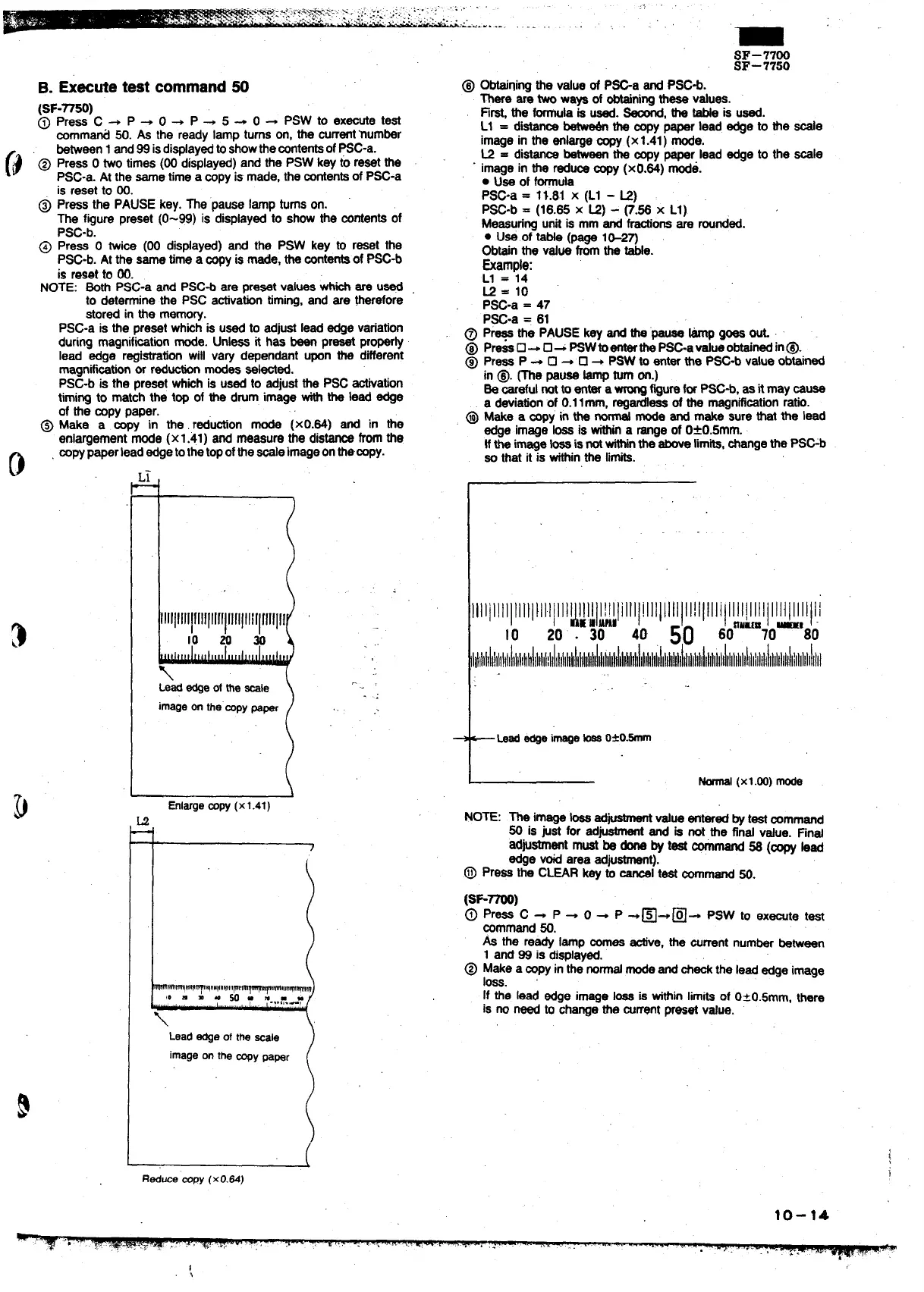
@ Make a’ b’~” in the. r~ution mode (xO.84) and in the
enlargementmode (x1.41) and measure the distanoefromthe
o
mpypaperlead edgetothetopofthe-e imageonthe-y.
L
lllllllllllllllllf!~ lllllllllllllll
10 m m
\
kk edgeoftheSIe
imageonthe”mpypaper .. .
I
(
R~um fflpy(xO.&)
SF-7700
SF–7750
@
Obteininothe value of P=a end PSC*.
There”ar; two ways of obtainingthese values.
Fi~ the formulais used. M, the tabte is used.
L1 = di~
betw~ the mpy paper lead edge to the -e
image in the enlargesopy (x1.41) mode.
L2 = dim betweenthe oopypaper lead edge to the
Soaie
image in the reclusesopy (xO.84) mode.
. Use of formula
PSC-a =
11.81 X (Ll - M)
PSC-b = (18.85 X U) - ~.~ X Ll)
Measuringunit is mm and frestionsare rounded.
● U*.of tsMe (page l&2~
Obtainthe value fromthe tie.
&le:
L1 = 14
K = 10
P~-a = 47
PSC-a = 61
@ Pr~ the PAUSE key and ti’pauee ~ goes U
@ Pm~U+U~~W@~h=-a@mobtiti in@.
@ Press P +
❑ 4 ❑ + PSW to enter the P~-b value obtained
in @. me pause ~p turnon.)
Se oarefulnotto entera- figurefor PSC*, as it may muse
a deviationof 0.1lmm, regard- of the rnagnifiation ratio.
@ we a -yin the_ mode and make sure that the lead
edge image ~ is tin a rangeof 0*0.5mm..
tfthe image~ isnotwfthinthe aboveMmits,~ange the PSGb
so that it is withinthe limits.
llllilllllllltl}llllltl~~l~l~~!lltItIIIllllllllll!lllllilllll[llllllltillllllll
10 20‘. 30
40
50 60aum70-’80
llitllliilll!ttIllltllllhl]llltllliltltltllillilht
t
Leadedgeimage_ O*O.-
I
Normal
(X1.oo)mode
NOTE: The image b ad-
value enteredby testoommand
50 is @et for ad”
~ and is not the find v*e. Find
ad~stment must be donsby test ~mand 5S (~ bad
edge void area adjuetmen~.
.@ press the CLEAR key ~
~1 test oorrrmand50.
As the ready lamp mea tive, the arrent numberbetween
1 and 99 is displayed.
@ Make a-yin the normalmodeand~-the Ieadedge image
loss.
If the lead edge image ~ is tithin limitsof 0~0.5mm, there
is no need to changethe mrrent preset Value.
10-14
1