24
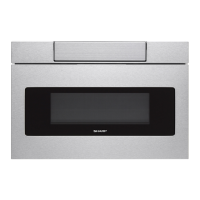
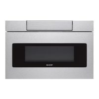
SMD2499FS
TEST PROCEDURES
PROCEDURE
LETTER
COMPONENT TEST
Disconnect the power supply cord and follow Drawer Disassembly Instructions.
Open the door and block it open. Discharge high voltage capacitor. Disconnect the leads to the primary
of the power transformer. Ensure that these leads remain isolated from other components and oven
chassis by using insulation tape. After that procedure, re-connect the power supply cord.
Check voltage between Pin No 3and Pin No 5 of the 7-pin connector (A) on the control unit with an
A.C. voltmeter.
The meter should indicate rated voltage, if not check oven circuit.
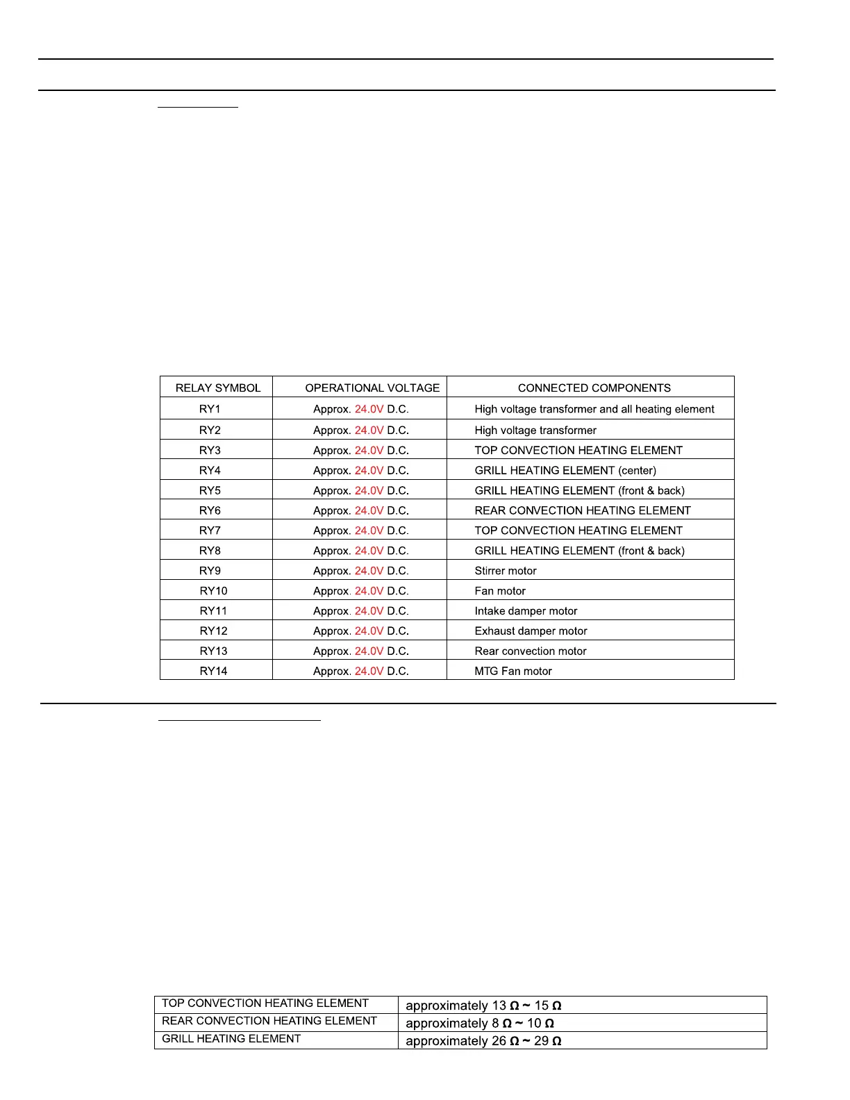
RY1, RY3 and RY4 Relay Test
These relays are operated by D.C. voltage
Check voltage at the relay coil with a D.C. voltmeter during the microwave cooking operation or heater
cooking operation.
DC. voltage indicated Defective relay.
DC. voltage not indicated Check diode which is connected to the relay coil. If diode is good,
control unit is defective.
Q RELAY TEST
R HEATING ELEMENT TEST
1. Disconnect the power supply cord, and then remove Top, Rear & Left outer case.
2. Open the door and block it open.
3. Discharge high voltage capacitor.
4. Make sure the heating element is fully cooled and test as follows:
a. Disconnect wire leads from the heating element and measure the resistance with an ohmmeter.
On the R x 1 scale, the resistance between the heating element terminals should be value as
following table.
b. Disconnect wire leads from the heating element and measure the insulation resistance with
500V - 100MΩ insulation resistance meter. The insulation resistance between heating element
terminal and cavity should be more than 0.5MΩ.
5. If the meter does not indicate above resistance, replace the heating element.
6. Reconnect all leads removed from components during testing.
7. Reinstall the outer case (cabinet).
8. Reconnect the power supply cord after the outer case is installed.
9. Run the oven and check all functions.