9
SX68JF100
9-1 9-2
Monocolor
screen
GREEN
Monocolor
screen
BLUE
Monocolor screen
release
Monocolor
screen
RED
90mm
ab
90mm
A=B
AB
A=B
AB
Fig. 8-1
Fig. 8-2: Rank A CRT
Fig. 8-3: Rank A CRT
Note:Set to natural magnetic field.
NO. Adjustment part Adjusting procedure and conditions Waveform and others
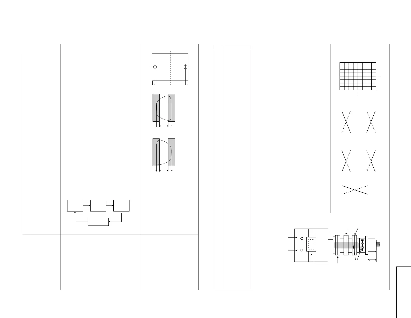
1 Purity
adjustment
1 Select the green monocolour screen with the
remote controller, and set the beam current of
1.4 mA with the contrast control.
2 Sufficiently degauss CRT with the degausing
coil.
Note:For the adjustable magnetic field, refer to
the job instruction sheet.
The adjustable magnetic field is as shown
page 5.
3 The purity magnet must be previously set at
the 0 magnetic field, and the convergence must
be adjusted to be rough.
With P-MG, adjust it to the center - rank A.
4 Observing the points a and b of Fig. 8-1 with
the microscope, move DY fore and aft to set
the landing at Rank A.
If the a/b balance is poor, compensate it to the
center “Rank AB”.
5 Align it to zero, keeping the raster rotation in
the east direction.
6 Tighten the deflection coil fastening screws.
Tightening torque: 108 ± 20N (11 ± 2 kgf)
7 Checking the CRT corner area, bond the mag-
netic sheet to set the landing at Rank A for
compensation.
Note: Apply the adjustment after aging with the
beam current 1,500 ± 50µA or more for 30
minutes or more.
Note: Select the service mode, and press the
monocolour key of R/C for process, and the
monocolour screen (green) will be selected.
* Every push of the monocolour key changes the
screen as follows.
PURITY ADJUSTMENT
2 Peripheral
purity
adjustment
1 After YPB adjustment of DY, receive the cross-
hatch, and coarsely adjust Yh and Yv by swing-
ing DY. (Fix it with the wedge within 30 sec-
onds.)
2 In the monocolour screen (green), set the
beam current at 1,400µA.
3 In Bh=0 and Bv= Refer to the factory setting
and geomagnetic adjustment by model (ref.),
verify that the landing in the corner area is prac-
tically at the rank A. If it is deviated, bond the
Pu compensation Mg for adjustment.
* Continuously press the monocolour
key 1 second or more, and the
monocolour mode will be selected
without the service mode.
Even with TEXT key or “R. G. Cy”
key, it can be directly switched to
each monocolour screen.
NO. Adjustment part Adjusting procedure and conditions Waveform and others
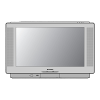
CONVERGENCE ADJUSTMENT
1 Convergence
adjustment
(Apply this after
purity
adjustment.)
1 Receive E-2CH (Crosshatch pattern).
2 With the remote controller, make it normal.
(Static convergence adjustment)
1 Overlap blue and red with the open-/closing
angle and rotation of the 4-pole magnet.
2 Overlap green on blue and red with the open-
/closing angle and rotation of the 6-pole mag-
net.
(Dynamic Convergence Adjustment)
1 Tilt the deflection yoke in all directions until the
vertical and horizontal lines become distortion-
free and straight on the screen. Fix the wedges
in this position.
2 Using the YH and YHC controls on the deflec-
tion yoke, adjust the red and blue vertical lines
along the Y axis at the screen center. (See
Figs. 9-1 and 9-2.)
3 If the red and blue horizontal lines (XV) along
the X axis at the screen center are out of
position, turn the balance coil on the deflec-
tion yoke to adjust the red and blue lines
(XV). (See Fig. 9-3.)
4 Looking all over the screen to make sure there
is no problem. Apply glass tape to the wedges
and apply lacquer to the deflection yoke lock
screws, magnet unit (purity, 4-pole and 6-pole
magnets), and magnet unit lock screws.
Fig. 9-2 Adjust with YH control.
Fig. 9-3 Adjust with balance coil.
Blue Red Red Blue
Blue
Blue Red Red Blue
X axis
Y axis
Fig. 9-1 Adjust with YHC control.
4-pole magnet
6-pole magnet
Purity magnet
Lacquer
30 ± 0.5mm
Balance coil
YHC
YH