18
XG-MB70X
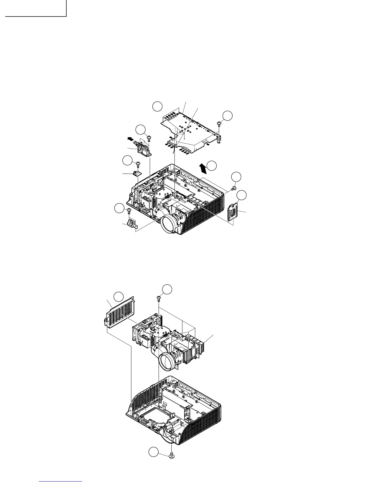
3. Removing the main PWB unit and the peripheral units
3-1. Remove 2 main PWB fixing screws (terminal side).
3-2. Remove 8 main PWB fixing screws.
3-3. Remove 14 connectors from the main PWB.
3-4. Pull out the switch bracket connector and remove 3 fixing screws.
3-5. Remove the fixing screw for the front R/C PWB.
3-6. Remove 2 fixing screws for the A/F holder unit.
3-7. Lift off the main PWB in an oblique direction from the optical mechanism unit side.
3-8. Remove the speaker holder ass’y.
4. Removing the optical mechanism unit
4-1. Remove the fixing screw for the optical mechanism unit from the bottom body.
4-2. Remove 5 fixing screws for the optical mechanism unit.
4-3. Remove the duct.
3-1
3-4
3-5
3-6
3-2
3-8
3-3
Main PWB Unit
Earth Lead Wire
Speaker
Holder
Ass’y
A/F Holder unit
Switch Bracket Unit
Front R/C PWB
3-7
[EA]
[AZ]
[AI]
[SO]
[TF]
[TO]
[FB]
[FA]
[FC]
[RA]
[DD]
[SC5001]
[CW]
[FD]
4-2
4-1
4-3
Duct
Optical Mechanism Unit