EasyManua.ls Logo

Sharp XL-DK225 User Manual

Sharp XL-DK225
75 pages
To Next Page IconTo Next Page
Page #1 background imageLoading...
Page #1 background image
XL-DK225
1
This document has been published to be used for
after sales service only.
The contents are subject to change without notice.
VID
EO
/
A
UX
PRECAUTIONS FOR USING LEAD-FREE SOLDER
CHAPTER 1. GENERAL DESCRIPTION
[1] Important Service Safety Precaution ........... 1-1
[2] Specifications............................................... 1-1
[3] Names Of Parts ........................................... 1-2
CHAPTER 2. ADJUSTMENTS
[1] CD Section .................................................. 2-1
[2] Test Mode .................................................... 2-2
[3] Standard Specification Of Stereo System
Error Message Display Contents ................. 2-4
CHAPTER 3. MECHANICAL DESCRIPTION
[1] Removing And Reinstalling The Main Parts
..................................................................... 3-1
[2] Disassembly ................................................ 3-2
CHAPTER 4. BLOCK DIAGRAM
[1] Block Diagram ............................................. 4-1
CHAPTER 5. CIRCUIT DESCRIPTION
[1] Waveforms Of Servo Circuit ........................ 5-1
[2] IC Voltage .................................................... 5-3
CHAPTER 6. CIRCUIT SCHEMATICS AND PARTS
LAYOUT
[1] Notes On Schematic Diagram ..................... 6-1
[2] Types Of Transistor And LED ...................... 6-1
[3] Schematic Diagram ..................................... 6-2
[4] Charts Of Connecting Wires ...................... 6-10
[5] Wiring Side of PWB ................................... 6-12
CHAPTER 7. FLOWCHART
[1] Troubleshooting ........................................... 7-1
CHAPTER 8. OTHER
[1] Function Table Of IC .................................... 8-1
[2] FL Display.................................................... 8-9
PARTS GUIDE
SERVICE MANUAL
No. S7734XLDK225/
Parts marked with " " are important for maintaining the safety of the set. Be sure to replace these parts with
specified ones for maintaining the safety and performance of the set.
CONTENTS
!
MICRO COMPONENT SYSTEM
MODEL
XL-DK225 Micro Component System consisting of
XL-DK225 (main unit) and CP-DK225 (speaker system).
XL-DK225
In the interests of user-safety (Required by safety regulations in
some countries) the set should be restored to its original condition
and only parts identical to those specified be used.
SHARP CORPORATION

Table of Contents

Question and Answer IconNeed help?

Do you have a question about the Sharp XL-DK225 and is the answer not in the manual?

Sharp XL-DK225 Specifications

General IconGeneral
BrandSharp
ModelXL-DK225
CategoryStereo System
LanguageEnglish

Summary

Precautions for Using Lead-Free Solder

Employing Lead-Free Solder

Discusses the use of lead-free solder in the unit's PWB and the identification symbol.

Using Lead-Free Wire Solder

Advises on using lead-free wire solder for repairs and the higher melting point.

Soldering Best Practices

Provides guidance on soldering techniques, tip maintenance, and cleaning.

Chapter 1. General Description

Important Service Safety Precautions

Outlines safety instructions for qualified service personnel and warnings against modifications.

Product Specifications

Details technical specifications for power, dimensions, weight, amplifier, tuner, speaker, and CD player.

Names Of Parts

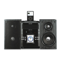
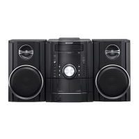
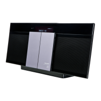
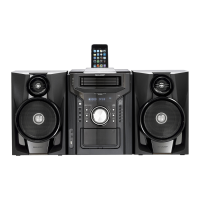
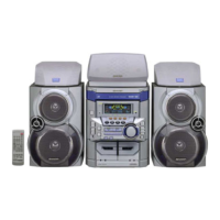
Identifies and labels various parts of the front, display, and rear panels of the unit.

Remote Control Overview

Remote Control Transmitter Functions

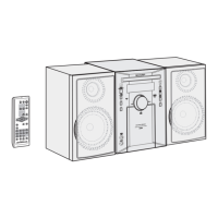
Lists and describes the functions of each button on the remote control transmitter.

Chapter 2. Adjustments

CD Section Adjustments

Explains automatic adjustment functions for the CD system and items adjusted automatically.

CD Error Code Descriptions

Lists CD error codes, their display messages, and explanations for mechanism errors.

Test Mode Operation

Details the procedure to enter and operate the CD test mode for diagnostics.

Standard Specifications and Error Messages

Covers stereo system error message display contents and procedures for transporting the unit.

Chapter 3. Mechanical Description

Removing and Reinstalling Main Parts

Provides instructions on how to remove the CD changer mechanism and discs.

Disassembly Procedures

Outlines step-by-step disassembly instructions for various unit components with caution notes.

Chapter 4. Diagrams

Main Block Diagram

Illustrates the overall system architecture, showing connections between major functional blocks.

CD Block Diagram

Details the block diagram for the CD and MP3 playback sections, including pickup and motor controls.

Chapter 5. Circuit Description

Waveforms of CD Circuit

Presents oscilloscope waveforms for various signals within the CD playback circuit for analysis.

Component Voltage Measurements

Lists voltage readings for various ICs and transistors in the circuit for diagnostic purposes.

Chapter 6. Circuit Schematics and Parts Layout

Notes on Schematic Diagrams

Explains symbols used in schematics for resistors, capacitors, and notes on voltage measurements.

Transistor and LED Types

Shows the physical appearance and pin configurations of transistors and LEDs used in the unit.

Schematic Diagrams

Provides detailed circuit schematics for different sections of the system, including tuner and power.

Charts of Connecting Wires

Illustrates wiring connections between various internal PWB units and external components.

Wiring Side of PWB

Shows the component layout and trace routing on the wiring side of various Printed Wiring Boards (PWBs).

Chapter 7. Flowchart

Troubleshooting Guide

Offers a step-by-step troubleshooting guide for common CD playback issues, including lens cleaning.

Focus-RF System Check

Details procedures for checking the Focus-RF system and associated waveforms for diagnostics.

Spin System and PLL System Checks

Outlines checks for the turntable spin system and PLL system, including waveform analysis.

Sharp Parts Guide

Integrated Circuits

Lists integrated circuits with their part codes, descriptions, and relevant markings.

Transistors

Lists transistors with part codes, descriptions, and markings for identification.

Diodes

Lists diodes with part codes, descriptions, and markings for identification.

Transformers and Coils

Lists transformers and coils with their part codes and descriptions for replacement.

Crystals, Capacitors

Provides part codes and descriptions for crystals and capacitors for servicing.

Resistors

Lists various resistors with their part codes, values, and power ratings for replacement.

Other Circuitry Parts

Lists various other circuitry components like connectors, fuses, and switches with their details.

Cabinet and CD Mechanism Parts

Details parts related to the unit's cabinet, chassis, and CD mechanism assembly.

Speaker Box Parts

Lists components and assembly parts for the speaker boxes, including drivers and enclosures.

Accessories, PWB Assemblies, and Other Service Parts

Lists accessories, packing parts, PWB assemblies, and other service parts.

Packing Method (For U.S.A. Only)

Unit Packing Procedure

Illustrates the method for packing the main unit and its accessories for shipping.

Front Speaker Packing Procedure

Details the method for packing the front speakers and their accessories.

How to Order Replacement Parts

Part Ordering Information

Provides instructions on how to order replacement parts, including required information.

Capacitor and Resistor Code Explanations

Explains the coding system used for identifying capacitor and resistor values and tolerances.

Related product manuals