SERVICE MANUAL
XL-DV60
No. S2517XLDV60//
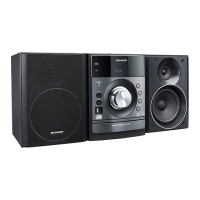
DVD MICRO SYSTEM
XL-DV60
MODEL
SHARP CORPORATION
CONTENTS
This document has been published to be used
for after sales service only.
The contents are subject to change without notice.
CHAPTER 1. GENERAL DESCRIPTION
[1] PRECAUTION FOR USING LEAD-FREE
SOLDER.........................................................1-1
[2] IMPORTANT SERVICE NOTES (FOR
U.S.A. ONLY)..................................................1-2
[3] SPECIFICATIONS..........................................1-3
[4] NAMES OF PARTS ........................................1-4
CHAPTER 2. ADJUSTMENTS
[1] ADJUSTMENT................................................2-1
[2] TEST MODE...................................................2-2
CHAPTER 3. MECHANICAL DESCRIPTION
[1] REMOVING AND REINSTALLING THE
MAIN PARTS..................................................3-1
[2] DISASSEMBLY...............................................3-2
CHAPTER 4. DIAGRAMS
[1] BLOCK DIAGRAM MAIN................................4-1
[2] BLOCK DIAGRAM TUNER/DISPLAY ............4-3
[3] BLOCK DIAGRAM DVD .................................4-5
CHAPTER 5. CIRCUIT DESCRIPTION
[1] VOLTAGE .......................................................5-1
CHAPTER 6. CIRCUIT SCHEMATICS AND PARTS
LAYOUT
[1] NOTES ON SCHEMATIC DIAGRAM .............6-1
[2] TYPES OF TRANSISTOR AND LED .............6-1
[3] SCHEMATIC DIAGRAM VIDEO TERMI-
NAL.................................................................6-2
[4] SCHEMATIC DIAGRAM MAIN/POWER
AMP...............................................................6-3
[5] SCHEMATIC DIAGRAM TUNER ..................6-5
[6] SCHEMATIC DIAGRAM DISPLAY................ 6-7
[7] SCHEMATIC DIAGRAM DVD1/3..................6-9
[8] SCHEMATIC DIAGRAM DVD2/3................ 6-11
[9] SCHEMATIC DIAGRAM DVD3/3................ 6-13
[10] WIRING SIDE OF PWB ............................. 6-15
[11] WIRING SIDE OF PWB MAIN TOP/POW-
ER AMP./JACK............................................6-17
[12] WIRING SIDE OF PWB MAIN BOTTOM......6-19
[13] WIRING SIDE OF PWB TUNER................. 6-21
[14] WIRING SIDE OF PWB DISPLAY/
SWITCH......................................................6-23
[15] WIRING SIDE OF PWB DVD TOP .............6-25
[16] WIRING SIDE OF PWB DVD BOTTOM...... 6-27
[17] WIRING SIDE OF PWB VIDEO TERMI-
NAL .............................................................6-29
CHAPTER 7. FLOWCHART
[1] TROUBLESHOOTING .................................. 7-1
CHAPTER 8. OTHERS
[1] FUNCTION TABLE OF IC.............................8-1
[2] FL DISPLAY.................................................. 8-5
Parts Guide
•
In the interests of user-safety the set should be restored to its origi-
nal condition and only parts identical to those specified be used.
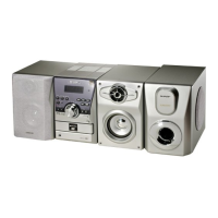
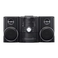
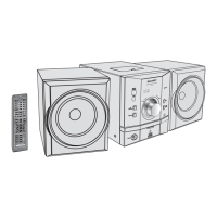
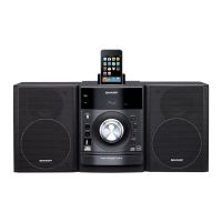
XL-DV60 DVD Micro System consisting of XL-DV60 (main
unit), CP-DV60F (front speakers) and CP-DV60SW(sub-
woofer).