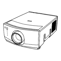
xv-zw99u
No. ( Adjustment Position
Adjustment Conditions
Adjustment Method
4 Video Color
@AC)
1. Receive the color bar signal. l Using the A and v keys, adjust the
2. Connect the oscilloscope between pin (1)
difference between the 100% white
of P3004 and GND.
level and the primary red level to
3. Press S2001 to call up the ADJ IN mode
0.0*0.05 v
and select the following subject.
100% White Red
Group: VIDEO 1
Subject: COLOR
5 Video Tint 1. Receive the color bar signal.
l Using the A and v keys, adjust the
@AC)
2. Connect the oscilloscope between pin (3)
(B-Y) signal waveform to slope down
of P3004 and GND.
straight.
3. Press S2001 to call up the ADJ IN mode
and select the following subject.
Group: VIDEO 1
Subject: TINT
0s
6
Component 1. Feed the NTSC lo-step pattern signal to
l Using the A and v keys, adjust the
Contrast (DAC)
the component terminal.
difference between the tenth-step
2. Connect the oscilloscope between pin (6)
level and the pedestal level to
of P3004 and GND.
1.3*0.05 vp-p.
3. Press S2001 to call up the ADJ IN mode
and select the following subject.
10
Group: COMPO
-c-
Subject: CONT
I
I
I
Il.3 vp-p
I
I
I
I
+
7 Component
AGC (DAC)
1. Receive the NTSC 1 O-step pattern signal.
l Using the A and v keys, adjust the
2. Connect the oscilloscope between pin (6)
difference between the tenth-step
of P3004 and GND.
level and the pedestal level to
3. Press S2001 to call up the ADJ IN mode
0.8kO.05 Vp-p.
and select the following subject.
10
Group: COMPO
-c -
Subject: CAGCADJ
I
I
I o.svp-p
I
I
I
I
+
24

 Loading...