34
Disassembly and inspection
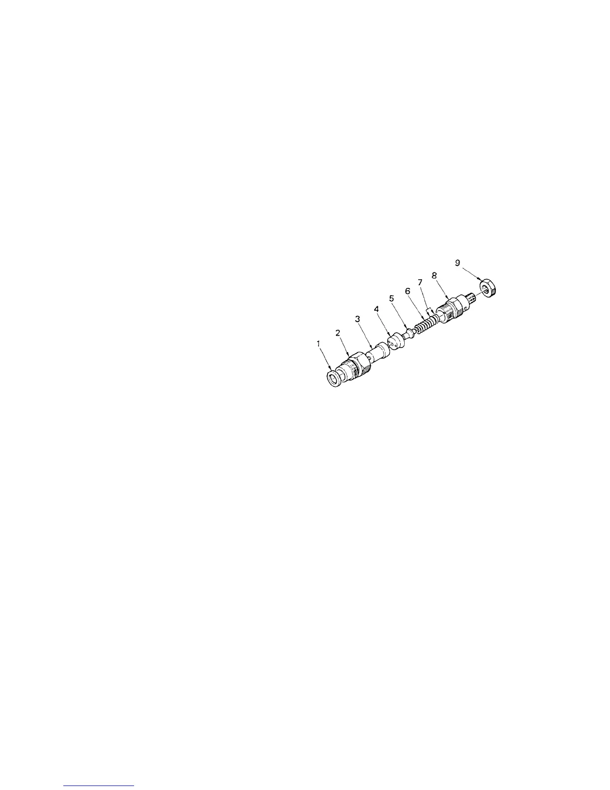
(1) Place the nozzle holder (body) in a vice and
disassemble turning the nozzle nut.
NOTE: Take care not to allow the needle valve to
drop when removing the nozzle.
(2) Wash the nozzle and needle valve and check for
seizure and sticking of the nozzle and fuel leakage on
the seat surface. Correct fuel leakage of the seat by
lapping.
(3) Check the distance piece upper and lower contact
areas and correct to be sticked closely.
(4) Check the push rod for wear on the nozzle needle
valve contact surface and check the spring seat for
crack.
Reassembly and adjustment
(1) When assembling a new nozzle ass’y, heat light oil to
50 - 60°C and remove the rust preventive oil in it.
Slide the body and needle valve to ensure that they
slide lightly.
(2) Invert the body, place the shim, spring, rod, piece and
nozzle on it in this order, cover the nozzle nut and
tighten.
(3) After assembly, check for the nozzle injection
pressure.
1. Adjust by the adjusting washer (shim) so that the
injection is started at 11.76 MPa {120 kgf/cm
2
}
using a nozzle tester.
2. The pressure increases or decreases about 0.98 MPa
{10 kgf/cm
2
} by a washer of 0.1 mm.
(4) Injection condition
1. Small drops should not be mixed in the spray.
2. The oil should be injected describing a cone by
straight lines toward the center line of the nozzle.
3. Place white paper at about 30 cm from the nozzle
and confirm that the spray is approximately circular
when injected.
4. Keep the oil pressure lower by 1.96 MPa {20
kgf/cm
2
} than the specified value 11.76 MPa {120
kgf/cm
2
} and check that the test oil does not drop
form the nozzle end.
153V
1. Gasket
2. Nozzle nut
Tightening torque: 29.4 – 49 N·m {3 – 5 kgf·m}
3. Nozzle
4. Piece
5. Rod
6. Spring
7. Shim
8. Body
9. Nut
Tightening torque: 29.4 – 39.2 N·m {3 – 4 kgf·m}


 To Next Page