81
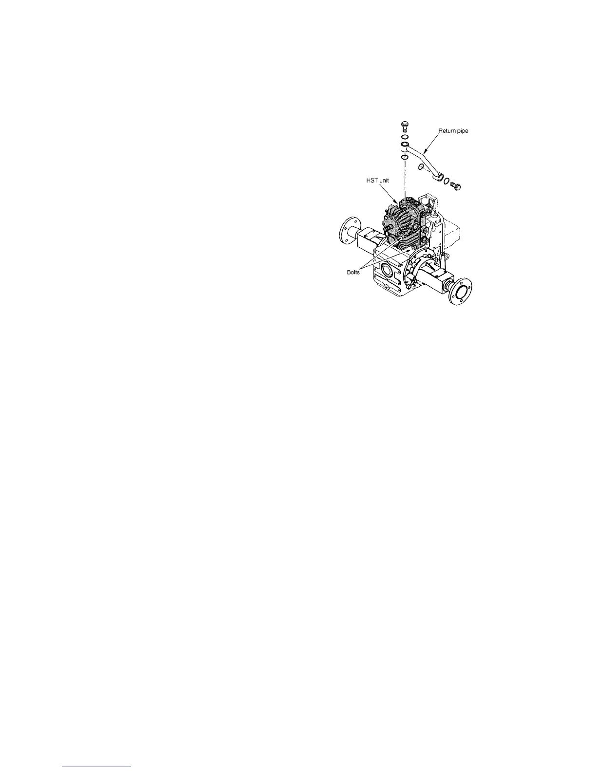
6) HST Unit
For removal and installation of the HST unit only, follows the step 1 to 7 of the “2. Removal and installation of front
axle and transmission, and HST unit” in Chapter 3-1 and refer to as follows:
1. Drain the transmission oil about 2 litters.
2. Disconnect the return pipe from top of the HST
unite.
3. Remove the four bolts for tightening HST unit to
transmission housing. (four bolts, return pipe,
HST unit)
4. Slide the HST unit forward and take out it.
437V
(1) Disassembly
Reference – Figure 440 V
★ Caution:
1. Never disassemble the HST unit during the claim warranty term. If it is disassembled, claim is
not accepted.
2. If disassembly is unavoidably required, the HST unit should be handled vary carefully since it is
finished precisely.
1. Remove the charge pump as follows:
➀ Remove the two socket head bolts (91), charge pump case (83) and O-ring (89) from the port block.
➁ Remove the trochoid rotor sub assembly (86).
➂ Remove the pin (87) from the shaft (8), and remove the plate (84), O-ring (90) and pin (88).
2. Remove the port block as follows:
➀ Remove the eight socket head bolts (55) and port block (2).
NOTE: Take care do not fall down the valve plates (6 and 7).
➁ Remove the pins (50), valve sub assembly (28), gasket (49) and spring (22).
➂ Remove the valve plates (6 and 7).
3. Remove the cylinder block assembly (3, 5, 20 and 41) for pump.
4. Remove the cylinder block assembly (3, 5, 20 and 41) for motor.
 Loading...