62
Unit Part Inspection Items
Standard
Dimension
Standard
Assembling Value
Repair Value
Service
Limit
Remarks
Torsion of large end and small end holes
(per 100 mm)
Less than 0.08 More than 0.2
Parallelism of large end and small end holes
(per 100 mm)
Less than 0.05 More than 0.15
Longitudinal play of connecting rod and crank pin 0.1 – 0.3 0.7
Clearance between connecting rod bearing and
crank pin
0.035 – 0.083 0.2 Oil clearance
Connecting rod tightening torque N⋅m {kgf
m}
29–34 {3.0–3.5}
Weight variation of piston after assembly (g) Less than 10
Journal dia.
No. 1, 2, 3
φ46
45.964 – 45.975
φ45.90 φ45.40
Undersize
(0.25, 0.5)
No. 4
φ46
45.954 – 45.965
Crank pin dia.
φ39 φ38.964 – 38.975 φ38.90 φ38.40
Undersize
(0.25, 0.5)
Journal and pin finishing accuracy 1.6Z
Run-out of crankshaft Less than 0.03 More than 0.06
Axial play of crankshaft 0.1 – 0.3 0.5
Thickness of No. 4 bearing holder 21.85 – 21.95 21.55
Bush (journal metal) bore × outside dia.
φ46×φ50
Under size
(0.25, 0.5)
Clearance between crank journal and bush
(journal metal)
0.039 – 0.092 0.2 Oil clearance
Center bearing (bore × outside dia.)
φ46×φ50
Undersize
(0.25, 0.5)
Clearance between crank journal and center
bearing
0.039 – 0.092
0.2
Upper
No.2,3
Lower No.4
Oil clearance
0.029 – 0.082
Bearing holder (upper and lower) tightening torque
N⋅m {kgf⋅m}
20–25 {2.0 – 2.5}
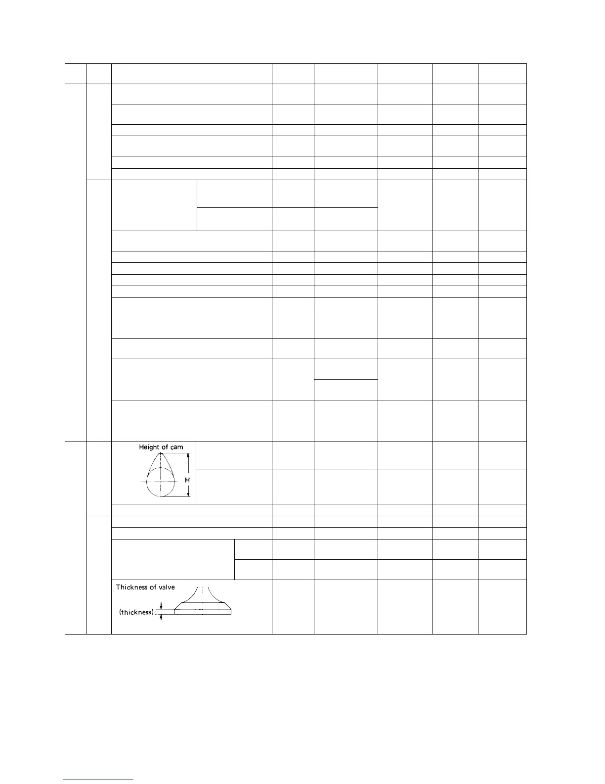
199V
For intake and exhaust
valves
26.565 – 26.62 26.1
For injection pump 33.94 – 34.06 33.8
Cam gear backlash 0.08 0.25
Intake valve stem 6.97 6.955 – 6.97 6.89
Exhaust valve stem 6.95 6.94 – 6.95 6.84
Clearance between valve stem and
valve guide
Inlet 0.03 – 0.06
More than
0.2
Exhaust 0.05 – 0.075
More than
0.25
200V
1.0 0.925 – 1.075 0.5
Valv e
Cam shaft
Valve system
Connecting rod
Crank shaft
Main moving part
 Loading...