EasyManua.ls Logo

Shimaden FP23 - User Manual

Default Icon
4 pages
Print Icon
To Next Page IconTo Next Page
Loading...
1
MFP023-E52-D
Dec. 2018
Contents may be changed for improvements without notice.
Copyright© SHIMADEN CO., LTD. All rights reserved.
FP23 2-input
Instruction Manual
http://www.shimaden.co.jp
For questions, please contact
YOUR LOCAL AGENT or
exp-dept@shimaden.co.jp
ڦPreface
Thank you for purchasing our product. Before you start to operate the product, please read
the following precautions at first, and use the product safely and carefully.
This Instruction Manual aims to summarize the Instruction Manual (Detailed version). For
detailed contents, please refer to the product’s original instruction manual (Detailed
version) which can be downloaded for free from our website http://www.shimaden.co.jp.
Documents/Application software available for download are as follows.
*FP23 series digital controller instruction manual (Detailed version) 2-input
*FP23 series digital controller Communication (interface) (RS-232C/RS-485)
instruction manual (Detailed version)
*Parameter setup tool “Parameter Assistant”
*USB setup software “USB SHIMADEN”
Operating environment
OS: Windows 7, Windows 10 (only 32-bit OS is supported)
Recommended CPU: Intel Celeron 700 MHz and above
Microsoft Windows, Windows 7 and Windows 10 are registered trademarks of
Microsoft Corporation in the United States and other countries.
ڦChecking accessories
Make sure that your product package has all of the following items
Standard accessories
(1) Instruction Manual (A3 size paper ×4)
(2) Mounting fixture (w/ 2 screws)
(3) Terminal cover
(4) Unit decal
Optional accessories
(1) Current transformer (CT) for heater break alarm (when the heater break alarm
option is selected)
(2) Terminal resistor (when the RS-485 communication option is selected)
ڦContents
Safety Precautions ................................................................................ 1
Precautions for Installation Site ............................................................. 1
Precautions for Wiring ........................................................................... 1
External Dimensions ............................................................................ 2
Panel Cutout Dimensions ...................................................................... 2
Mounting................................................................................................ 2
Rear Terminal Arrangement Diagram ................................................... 2
Wiring Example of Open Collector Output ............................................. 2
Names and Functions of Parts on Front Panel ...................................... 3
Error Messages ..................................................................................... 3
LCD Flow Chart ..................................................................................... 4
Frequently-used Keys for LCD .............................................................. 4
ڦSafety Precautions
Warning
The FP23 Series Digital Controller is control instruments designed for industrial use to control
temperature, humidity and other physical quantities in general industrial facilities. It must not be used
in any way that may adversely affect the safety, health or working conditions of those who come into
contact with the effects of its use. When used, adequate and effective safety countermeasures must
be provided at all times by the user. No warranty, express or implied, is valid when this device is
used without the proper safety countermeasures.
Before you start to use this device, install it in a control panel or the like and avoid touching the
terminals.
Do not open this device's case, and touch the boards or inside of the case with your hands or a
conductor. The user should never repair or modify this device. Doing so might cause an
accident that may result in death or serious bodily injury from electric shock.
Caution
To avoid damage to connected peripheral devices, facilities or the product itself due to malfunction of
this device, safety countermeasures such as proper installation of the fuse or installation of
overheating protection must be taken before use. No warranty, express or implied, is valid in the
case of use resulting in an accident without having taken the proper safety countermeasures.
The warning mark on the plate affixed on the casing of this device warns you not to touch
charged parts while this device is powered ON. Doing so might cause an electric shock.
A means for turning the power OFF such as switch or a breaker must be installed on the
external power circuit connected to the power terminal on this device. Fasten the switch or
breaker at a position where it can be easily operated by the operator, and indicate that it is a
means for powering this device OFF.
This device does not have a built-in fuse. Install a fuse that conforms to the following rating in
the power circuit connected to the power terminal.
Fuse rating/characteristics: 250 VAC 1.0A/medium lagged or lagged type
When wiring this device, tighten the terminal connections firmly.
Use the device with the power voltage and frequency within their rated ranges.
Do not apply a voltage or current outside of the input rating to the input terminal. Doing so
might shorten the service life of this device or cause it to malfunction.
The voltage and current of the load connected to the output terminal should be within the
rated range. Exceeding this range may cause the temperature to rise which might shorten the
service life of this device or cause it to malfunction.
This device is provided with ventilation holes for heat to escape. Prevent metal objects or
other foreign matter from entering these ventilation holes as this may cause this device to
malfunction. Do not block these ventilation holes or allow dirt and dust to stick to these holes.
Temperature buildup or insulation failure might shorten the service life of this device or cause
it to malfunction.
Repeated tolerance tests on voltage, noise, surge, etc. may cause this device to deteriorate.
Never remodel this device or use it a prohibited manner.
To ensure safe and proper use of this device, and to maintain its reliability, observe the
precautions described in this manual.
Do not operate the keys on the front panel of this device with a hard or sharp-tipped object. Be
sure to operate the keys with your fingertips.
When cleaning this device, do not use paint thinner or other solvents. Wipe gently with a soft,
dry cloth.
It takes 30 minutes to display the correct temperature after applying power to the digital controller.
(Therefore, turn the power on more than 30 minutes prior to the operation.)
ڦPrecautions for Installation Site
Caution
Do not use this device in the following sites. Doing so might result in malfunction or damage to
this device and in some cases cause fire and/or dangerous situations.
Locations that are filled with or generate inflammable gas, corrosive gas, dirt and dust,
smoke, etc.
Locations that are subject to water droplets, direct sunlight or strong radiated heat from
other equipment
Locations where the ambient temperature falls below -10°C or rises above 50°C
Locations where dew condensation forms and the humidity reaches 90% or more
Near equipment that generates high-frequency noise
Near heavy current circuits or locations likely to be subject to inductive interference
Locations subject to strong vibration and impact
Locations exceeding an elevation of 2000 m
ڦPrecautions for Wiring
Caution
To prevent electric shock, always turn off and disconnect this device from the power supply
before starting wiring.
Do not touch wired terminals or charged parts with your hands while the power is supplied.
Pay attention to the following points when performing wiring:
Check that the wiring is free from mistakes according to " Rear Terminal Arrangement
Diagram."
Use crimped terminals that accommodate an M3 screw and that have a width of 6.2 mm or
less.
For thermocouple input, use a compensation wire compatible with the type of thermocouple.
For RTD input, the resistance of a single lead wire must be 10ȍ or less and the three wires
must have the same resistance.
The input signal lead must not be passed along the same conduit or duct as that for
high-voltage power lines.
Shield wiring (single point grounding) is effective against static induction noise.
Short interval twisted pair wiring is effective against electromagnetic induction noise.
When wiring, use wire or cable (minimum 1 mm
2
cross-sectional area) of 600 V grade PVC
insulated wire or equivalent wire having the same rating.
For wiring the ground, ground the ground terminal with the earth resistance at less than
100ȍ and with wire 2 mm
2
or thicker.
Two earth terminals are provided, each connected internally. One is for the ground
connection, and the other is for connecting the shield of the signal lead. Do not use the
earth terminals for crossover wiring of the power system ground lead.
If this device is considered as being susceptible to noise caused by the power supply,
attach a noise filter to prevent abnormal functioning.
Install a noise filter onto a grounded panel, and make the wire connecting the noise filter
output and the power supply terminal on this controller as short as possible.
㼀㼑㼞㼙㼕㼚㼍㼘㻌㼞㼑㼟㼕㼟㼠㼛㼞㻌㼒㼛㼞㻌㼏㼛㼙㼙㼡㼚㼕㼏㼍㼠㼕㼛㼚㻌㻌
㻔㼛㼜㼠㼕㼛㼚㼍㼘㻕

Other manuals for Shimaden FP23

Question and Answer IconNeed help?

Do you have a question about the Shimaden FP23 and is the answer not in the manual?

Summary

Preface

Safety Precautions

Precautions for Installation Site

Precautions for Wiring

External Dimensions

Panel Cutout Dimensions

Mounting

Wiring Example of Open Collector Output

Rear Terminal Arrangement Diagram

Names and Functions of Parts on Front Panel

OPV display

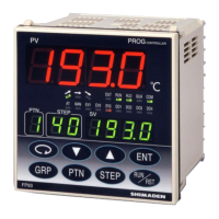
Displays measurement or error messages for CH1 or CH2 in 2-loop spec.

DSV display

Displays target set values for CH1 or CH2 in 2-loop spec.

LCD display

Main display showing pattern, output, channel, or input status.

Front panel key switches

Controls for navigating screens and changing parameters.

LED indicators

Status indicators for program, hold, manual, fix, and output actions.

Monitor lamps (2-input specification only)

Displays CH2 PV/SV values or CH2 PV on SV display.

Error Messages

LCD Flow Chart

Frequently-used Keys for LCD

Overview

FP23 2-input Digital Controller

The FP23 2-input Digital Controller is a sophisticated control instrument designed for industrial applications, primarily for managing temperature, humidity, and other physical quantities in general industrial facilities. It is crucial to understand that this device is intended for industrial use and should not be employed in ways that could compromise safety, health, or working conditions. Users are responsible for implementing adequate and effective safety measures when operating this device. Any use without proper safety countermeasures will invalidate the warranty.

Function Description

The FP23 2-input Digital Controller offers comprehensive control and monitoring capabilities, making it suitable for a wide range of industrial processes.

Control Modes: The device supports various control modes, including program control, manual operation, and fixed setpoint (FIX) control. In program control, the controller executes a predefined sequence of steps, each with its own setpoint and duration. The "Remaining step time display" feature shows the time left for the current step during program operation, aiding in process management. The "Pattern graph display" visually represents the pattern (step) graph during program operation, providing an intuitive overview of the control process.

Input and Output: The FP23 supports two input channels (IN1/IN2 PV) for measuring process variables, making it a 2-input specification device. It can handle various input types, including mV, thermocouple, RTD, V, and mA signals. For thermocouple inputs, compensation wires compatible with the specific thermocouple type must be used. For RTD inputs, the resistance of a single lead wire must be 100 Ω or less, and all three wires must have the same resistance to ensure accuracy.

The controller provides multiple output options, including analog outputs (current or voltage), and external control outputs (DO). The external control outputs include Darlington outputs (DO1 to DO3) and open collector outputs (DO4 to DO8, and DI5 to DI10). These outputs can be used to drive relays, SSRs, or other external devices. The brightness of the output lamps (OUT1, OUT2) changes according to the fluctuation of the control output for current/voltage outputs, and they light up when the output is ON for contact/SSR drive voltage outputs.

Alarm Functions: The device includes a heater break alarm option, which can be configured with a current transformer (CT) for monitoring heater status. This feature enhances safety by detecting potential issues with heating elements.

Communication: The FP23 supports RS-232C and RS-485 communication interfaces, allowing for integration into larger control systems. A terminal resistor is available as an optional accessory for RS-485 communication. The "Communication function" (SG+, SD+, RD-) terminals facilitate data exchange with external systems. The "COM" lamp lights up during communication mode, indicating active data transfer.

Display Modes: The controller features an LCD display (21 characters x 4 lines, max.) and LED indicators for clear status monitoring. For 2-loop specifications, there are three display modes, which can be switched using the DISP key on the front panel:

  • Display mode 1: Shows the current measured value (PV) or an error message of CH1, and the target set value (SV) of CH1.
  • Display mode 2: Shows the current measured value (PV) or an error message of CH2, and the target set value (SV) of CH2.
  • Display mode 3: Shows the current measured value (PV) or an error message of CH1, and the target set value (SV) of CH2.

The LED indicators (RUN, HLD, MAN, FIX, EXT, AT, EV1, EV2, EV3, DO1-DO5, COM, CH2, PV) provide quick visual feedback on the device's operational status, control actions, and alarm conditions. For instance, the RUN lamp lights green during program execution, the HLD lamp lights green when the program is paused, and the MAN lamp blinks green when control output is set to manual operation. The EXT lamp lights green when pattern number selection is active.

Parameter Setup: Parameters can be selected and displayed through the front key operation. The "Parameter Assistant" setup tool and "USB SHIMADEN" software are available for easier configuration via a computer.

Usage Features

Installation: The FP23 is designed for panel mounting. Users must drill mounting holes according to the panel cutout dimensions provided in the manual. The applicable thickness of the mounting panel is 1.0 to 8.0 mm. The device is pressed into the panel from the front, and mounting fixtures are inserted at the top and bottom from behind, then tightened with screws to secure the device. Care must be taken not to overtighten the screws, as this may deform or damage the device housing. After wiring, the terminal cover should be attached.

Wiring: Wiring must be performed with the power supply turned off and disconnected to prevent electric shock. Crimped terminals accommodating M3 screws with a width of 6.2 mm or less should be used. Input signal leads should not be routed along the same conduit or duct as high-voltage power lines. Shield wiring (single point grounding) is effective against static induction noise, and short interval twisted pair wiring is effective against electromagnetic induction noise. For ground wiring, the ground terminal should be connected with an earth resistance of less than 100 Ω using a wire of 2 mm² or thicker. If the device is susceptible to power supply noise, a noise filter should be attached to a grounded panel, with the wire connecting the noise filter output and the power supply terminal on the controller kept as short as possible.

Operation: The front panel features several keys for intuitive operation:

  • DISP: Displays the basic screen and switches the display mode.
  • GRP: Changes the screen group or returns to the screen group top screen.
  • SCRN: Switches the parameter display screen within a screen group.
  • Up/Down arrows: Select parameters, move the digit in set numerical values, and increment/decrement parameters and numerical values during setup.
  • ENT: Registers data or parameter numerical values.
  • STEP: Increments the start step number in the basic screen (requires ENT to register).
  • PTN: Increments the start pattern number in the basic screen (requires ENT to register).

Key combinations like ENT + PTN enable "Hold (HLD) operation," and ENT + STEP enable "Advance (ADV) operation."

Environmental Considerations: The device should not be used in locations with inflammable or corrosive gases, dirt, dust, smoke, water droplets, direct sunlight, strong radiated heat, or high-frequency noise. It should also be protected from ambient temperatures outside the -10°C to 50°C range, dew condensation, humidity exceeding 90%, strong vibration, impact, or elevations exceeding 2000 m. These conditions can lead to malfunction, damage, or dangerous situations.

Maintenance Features

Troubleshooting and Error Messages: The device displays error codes on the PV display to indicate malfunctions. These codes include:

  • E-rAn (ROM error)
  • E-rAM (RAM error)
  • E-EEP (EEPROM error)
  • E-Rd1 (Input 1 A/D error)
  • E-Rd2 (Input 2 A/D error)
  • E-5Pc (Hardware error)

If any of these messages appear, all outputs will turn OFF or become 0%. In such cases, repair or replacement is required, and users should immediately turn off the power and contact their dealer.

Other error codes related to PV input abnormalities include:

  • 50.LL: PV value exceeded the measuring range lower limit (-10%FS).
  • 5C.HH: PV value exceeded the measuring range higher limit (+110%FS), RTD-A burnout, or thermocouple burnout.
  • 6: One or two RTD-B burnout, or all leads of the RTDs burnout.
  • CULL: Reference junction compensation (-20°C) is at the lower limit (thermocouple input).
  • CU.HH: Reference junction compensation (+80°C) is at the higher limit (thermocouple input).

When these codes appear, users should check the input or heater lead. If the issue persists, contacting the dealer is recommended.

Heater Current Abnormality: The code H6 HH indicates that the heater current exceeds 55.0A. This error code is displayed on the LCD when a heater current abnormality is detected during control execution.

Cleaning: When cleaning the device, users should not use paint thinner or other solvents. Instead, wipe gently with a soft, dry cloth.

Ventilation: The device is equipped with ventilation holes to dissipate heat. It is crucial to prevent metal objects or other foreign matter from entering these holes, as this can cause malfunction. The ventilation holes should not be blocked, and dirt or dust should not accumulate on them, as this can lead to temperature buildup or insulation failure, shortening the device's service life.

Power-On Stabilization: It takes approximately 30 minutes for the digital controller to display the correct temperature after applying power. Therefore, it is recommended to turn on the power more than 30 minutes prior to operation.

General Safety: Users should never open the device's case or touch the boards or internal components with their hands or any conductor, as this could result in electric shock, serious bodily injury, or death. The device does not have a built-in fuse; therefore, a fuse conforming to the rating of 250 VAC 1.0A (medium lagged or lagged type) must be installed in the power circuit connected to the power terminal. A means for turning the power OFF, such as a switch or breaker, must be installed on the external power circuit connected to the power terminal. This switch or breaker should be easily operable and clearly indicated as the power-off means for the device. The device should be used within its rated power voltage and frequency ranges. Applying voltage or current outside the input rating to the input terminal can shorten the device's service life or cause malfunction. Similarly, the voltage and current of the load connected to the output terminal should be within the rated range to prevent overheating and malfunction. The keys on the front panel should be operated with fingertips, not with hard or sharp-tipped objects. The device should never be remodeled or used in a prohibited manner. Repeated tolerance tests on voltage, noise, surge, etc., may cause the device to deteriorate.

Shimaden FP23 Specifications

General IconGeneral
ModelFP23
TypeTemperature Controller
Input TypeThermocouple, RTD, DC Voltage
Output TypeRelay, DC Current
DisplayLED
Power Supply100 to 240 VAC
Control MethodPID
Accuracy±0.3% of FS
Operating Temperature50 °C

Related product manuals