4. Installation and Wiring
4-1.Installation Site
(1) Where flammable gas, corrosive gas, oil mist and particles that can
deteriorate electrical insulation are generated or are abundant.
(2) Where the temperature is below -10°C or above 50°C.
(3) Where the relative humidity is 90%RH or below dew point.
(4) Where highly intense vibration or impact is generated or transferred.
(5) Near high voltage power lines or where inductive interference can
affect the operation of the product.
(6) Dew drops or direct exposure to sun light.
(7) Where the elevation is in excess of 2,000 m.
4-2.Mounting
(1) Cut a hole for mounting the controller in the panel with reference to
the cutout drawing shown in section 4-4 on page 3.
(2) The panel thickness should be 1.0~3.5 mm.
(3) As the instrument is provided with pawls for fixing, mount it by
pressing it firmly from the front of the panel.
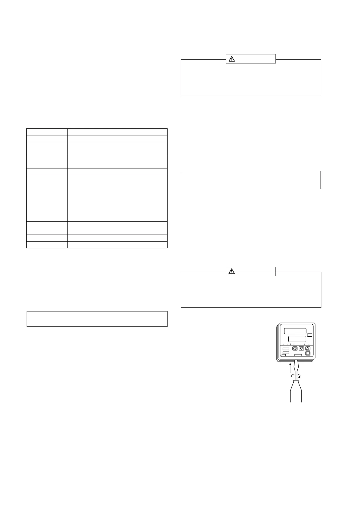
4-3.How to Take the Controller out of the Case
Under ordinary circumstances, the SR 60
series controller need not be taken out of its
housing. However, if such a step is necessary
for the purpose of replacement or the like,
follow the procedure described below.
Insert a screwdriver with a tip width of 6 to 9
mm into a notch (where the packing is
exposed) on the bottom of the casing and
rotate the screw driver while pressing up the
lock lever behind the packing. When the
controller body comes out of the housing by a
few mm, use your hand to pull it out
completely.
4-4.External Dimensions and Panel Cutout
Please refer to section 4-4 on page 3.
- 5 -
3. Introduction
3-1. Check before Use
This product has been fully checked for quality assurance prior to
shipment. Nevertheless, you are requested to make sure that there is no
error, damage or shortage of delivered items by confirming the model
codes and checking the external view of the product and the number of
accessories.
Confirmation of Model Codes:
Check the model codes stuck to the case of the product to ascertain if
respective codes designate what was specified when you ordered the
product, referring to the following code table:
Accessories to be checked:
Instruction manual 1 set
Unit decal 1 sheet
Current transformer (CT) for heater break alarm: included with the heater
break alarm option
TYPE CTL-6-S for 30A selection
TYPE CTL-12-S36-8 for 50A selection
3-2.Handling Instructions
(1) Do not operate the keys on the front panel with a hard or sharply
pointed object. Operate the keys only by softly touching them with
your finger tips.
(2) When cleaning the controller, wipe it softly with a dry cloth. Never
use solvent such as thinner or the like.
Note: Contact our representative concerning any problems with the
product, accessories or related items.
When selecting a site for the controller, avoid the places mentioned
below. Selection of these places may result in a malfunction or
damage to the controller, including the worse case of fire, depending
on the circumstances.
CAUTION
Note: The environmental conditions belong to the installation
category II of IEC 664 and the degree of pollution is 2.
When taking the controller out of the housing or reassembling it in
place, make sure the power supply is switched off. If the power is
not switched off, a malfunction or damage to the controller may
result.
CAUTION
DISP
AT
PV
SV
ENT
OUT AH AT MAN SB
AL EV/HB
Code and DescriptionItem
1. Series
2. Input
3. Control output
4. Power supply
6. Analog output
7. Set value bias
8. Remarks
SR62, SR63, SR64
90: 100~240V AC 10: 24V AC 02:24V DC
Y1: Contact I1: Current P1: SSR drive voltage
V1: Voltage
1: Thermocouple 2. R.T.D. 3. Voltage (mV)
4. Current (mA) 6. Voltage (V)
00: Without
03: Higher/lower limit alarm
12: Higher/lower limit alarm + event output
13: Higher/lower limit alarm + heater break alarm (30A)
14: Heater break alarm (30A)
15: Higher/lower limit alarm + heater break alarm (50A)
16: Heater break alarm (50A)
5.
0: Without 3: Voltage (mV) 4: Current (mA)
6: Voltage (V)
Alarm/event/
heater break
alarm (Heater
break alarm can
be selected if
Y1 or P1 is
selected for
item 3 above.)
0: Without 1: With
C: Without (CE marking) 9: With