This document serves as a Dealer's Manual for Shimano GRX front derailleurs, specifically covering models FD-RX810 and FD-RX400. It is primarily intended for professional bicycle mechanics due to the technical nature of the installation and adjustment procedures. Users without professional training in bicycle assembly are advised against attempting the installation themselves and should consult a place of purchase or a bicycle dealer for assistance if any part of the manual is unclear.
Function Description
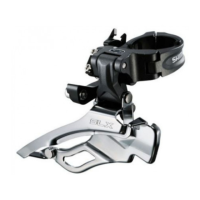
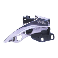
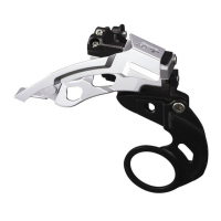
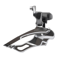
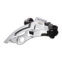
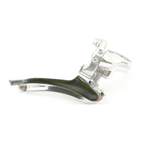
The Shimano GRX front derailleur is a component designed to facilitate gear shifting on bicycles, specifically for road, MTB, trekking, city touring/comfort bike, and urban sport categories. Its primary function is to move the bicycle chain between different chainrings on the crankset, allowing the rider to select appropriate gear ratios for varying terrain and riding conditions. The derailleur works in conjunction with a dual control lever, which the rider operates to initiate gear changes. Proper installation and adjustment are crucial for smooth and reliable shifting performance. The manual details the steps for installing the derailleur, securing the inner cable, and fine-tuning the shifting mechanism to ensure optimal operation.
Usage Features
The manual emphasizes several key aspects for correct usage and optimal performance:
- Installation Height Adjustment: The front derailleur's installation height must be adjusted so that the distance from the tips of the teeth of the largest chainring to the chain guide outer plate is between 1 and 3 mm. This precise positioning is critical for effective chain movement between chainrings.
- Chain Guide Position Adjustment: The chain guide's position needs careful adjustment using the low adjustment bolt. The front end of the chain guide outer plate should align with the surface of the largest chainring, and its rear end should be 0.5 - 1.0 mm inside. This ensures the chain moves smoothly without rubbing or falling off.
- Support Bolt Adjustment: For brazed-on type frames, a backup plate must be installed to prevent damage from the front derailleur's support bolt. The support bolt should be adjusted so that the flat portion of the chain guide outer plate aligns with the surface of the largest chainring, ensuring the support bolt is in contact with the backup plate.
- Cable Routing and Tension: The inner cable must be routed correctly through the front derailleur, ensuring it passes through the groove and the cable guide. Cable tension is a critical adjustment. After operating the release lever to the initial position (smallest chainring side) and removing the link cover, the cable is passed through the derailleur. The adjustment barrel protrusion must be in contact with the input link. The cable is then temporarily fixed, and any initial extension is removed before securing the cable with the cable fixing bolt.
- Cable Tension Adjustment: Cable tension is adjusted using the cable adjustment barrel or a cable adjuster on the frame. The indicator lines of the bracket and input link must be aligned when the lever is released from the top position to the T-trim position. This ensures the correct baseline tension for shifting.
- Top Adjustment: This adjustment sets the limit for the chain's outward movement. After aligning the chain with the largest sprocket, the top adjustment bolt is used to set the clearance between the chain guide inner plate and the chain to 0 – 0.5 mm. This prevents the chain from overshifting and falling off the largest chainring.
- Low Adjustment: This adjustment sets the limit for the chain's inward movement. After aligning the gear where the lever is released from the low side to the L-trim position, the low adjustment bolt is used to set the clearance between the skid plate of the chain guide and the chain to 0 – 0.5 mm. This prevents the chain from overshifting and falling off towards the bottom bracket.
- Chain Guide Clearance: The manual specifies precise clearances (0-0.5 mm) between the chain guide and the chain for both top and low adjustments, which are crucial for smooth and quiet operation.
- Cable End Handling: After installation and adjustment, any excessive cable should be run through the hole in the link cover, the link cover reinstalled, and the cable then cut and fitted with an end cap.
- Gear Shifting Check and Fine Tuning: After installation, the gear shifting should be checked by operating the shifting lever. The manual provides a troubleshooting guide for common shifting issues:
- If the chain falls to the crank side, turn the top adjustment bolt counterclockwise.
- If shifting is difficult from the smallest to the largest chainring, turn the top adjustment bolt clockwise.
- If shifting is difficult from the largest to the smallest chainring, turn the top adjustment bolt counterclockwise.
- If the chain falls to the bottom bracket side when shifted to the lowest position, turn the top adjustment bolt clockwise.
- If the chain falls to the bottom bracket side when shifted to the L-trim position, turn the low adjustment bolt clockwise.
- It is important to check the cable tension using the indicator and perform these checks if shifting becomes difficult during use.
- Shimano Genuine Parts: The manual recommends using only SHIMANO genuine parts to ensure safety and proper function. Loose or damaged parts can lead to serious injury.
- Safety Glasses: Users are advised to wear safety glasses or goggles when performing maintenance tasks.
- Chain Catching: Riders should be careful not to let clothing get caught in the chain while riding, as this could cause a fall.
- Chain Noise: If the chain generates noise when in certain positions (e.g., cross-chaining), the rear sprocket should be shifted to the next largest gear or the one after to alleviate the issue.
- Cable and Casing Lubrication: For smooth operation, an OT-SP sealed cable and cable guide should be used. The inner cable and sliding portions of the outer casing should be greased. If the grease wears off, SIS SP41 grease (Y04180000) is recommended.
- Cold Region Use: In cold regions, a sealed outer cap (resin type) should be used to prevent freezing.
- Derailleur Wear: If looseness in the derailleur links is so great that gear shifting adjustments cannot be made, the derailleur should be replaced.
Maintenance Features
The manual includes a section on maintenance, specifically focusing on replacing the skid plate:
- Removing the Skid Plate: To remove the skid plate, a slit should be made in it at the illustrated position using nippers, and then the skid plate can be removed.
- Installing the Skid Plate: A new skid plate is installed by inserting it into the mounting hole. It is crucial to check that the claws on the skid plate are properly engaged on the back side of the inner plate.
- Skid Plate Limitation: The manual explicitly states that the skid plate on the outer plate side cannot be replaced.
- Cleaning and Lubrication: If gear shifting operations are not smooth, the derailleur should be cleaned, and all moving parts lubricated. This is a general maintenance tip to ensure continued optimal performance.