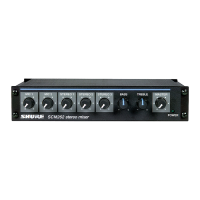
5. Slide the back panel and pc board out from the rear of the chassis.
When reassembling the SCM262, DO NOT OVERTIGHTEN the knob retainer nuts. Use a minimal amount of
force to secure the nut (0.6-0.8 N-m (5-7 in-lb)). Damage to the internal components will result if too much
force is used.
Mono Mixer Modification
This modification allows all the inputs to be mixed to a single mono signal sent over both the left and right
outputs.
Short jumper X203.
Phantom Power Disable
This modification disables the phantom power per channel.
To disable the phantom power from mic 1, remove resistor R121. To disable the phantom power from mic 2,
remove resistor R122.
15 dB Mic Preamplifier Pad
When a microphone has an extremely high signal, getting the desired gain might be difficult - a small turn of the
gain control might change the sound from a whisper to deafeningly loud. This modification adds a 15 dB Mic
preamplifier pad to allow more accurate gain adjustment with extremely high microphone signals.
Remove R160 (mic 1) or R183 (mic 2).
Hard Panning MIC Channels
To remove MIC 1 from the left outputs, remove R912. To remove MIC 1 from the right outputs, remove R913.
To remove MIC 2/LINE 2 from the left outputs, remove R910. To remove MIC 2/LINE 2 from the right outputs,
remove R911.
Low-Cut Filter
To eliminate the 80 Hz, low-cut filter, remove resistor R501 (mic 1), or resistor R519 (mic 2). Place a 10 to 33 µF
capacitor in X501 (mic 1) or R502 (mic 2). The polarity of the capacitor does not matter. To change the frequency
of the low cut filter, remove resistor R501 (mic 1) or R519 (mic2), and place the proper capacitor into X501 (mic 1)
or X502 (mic 2) to get the desired corner frequency.
The following tables list the low-cut frequency corners for some of the most common capacitor values:
Capacitor Value
Corner Frequency
Publications

 Loading...