9
sync
ENTER
EXITEXIT
SCANSCAN
powercontrol
push
RF
A B
audio gain
OL
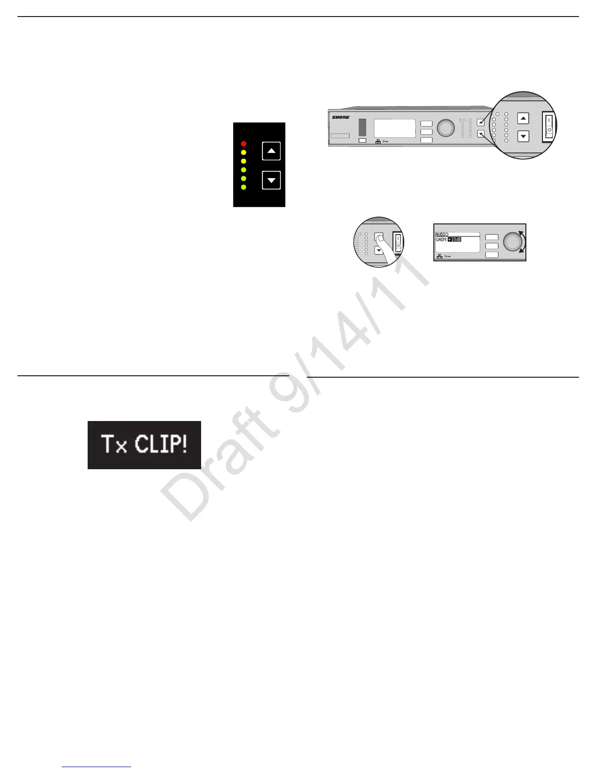
Setting Gain
Adjust gain at the receiver so that the average signal levels are solid green
and yellow with peaks that flicker the red overload LED. Attenuate the gain if
the signal overloads repeatedly.
Set the XLR output to line-level when possible to optimize noise performance.
Receiver Gain Controls
The receiver adjusts the system audio gain from 0 to +60 dB. No transmitter
gain is necessary to optimize the gain structure. This allows you to make ad-
justments during a live performance.
ULXD4
Digital Wireless Receiver
sync
push
control
ENTER
EXIT
SCAN
RF
A B
OL
OL
gain poweraudio
ULXD4
Digital Wireless Receiver
sync
push
control
ENTER
EXIT
SCAN
Adjust Gain at the Receiver
Pressthe▲▼gain buttons on the front of
the receiver to adjust in 1 dB increments.
Large Gain Adjustments
Press and hold a
gain button
or
Use the control wheel in
the
AUDIO menu
Reading the Audio Meter
Audio peaks illuminate the LEDs for 2 seconds while RMS
signal is displayed in realtime.
OL (Overload) LED: Illuminates red when the internal limiter
is engaged, preventing digital clipping.
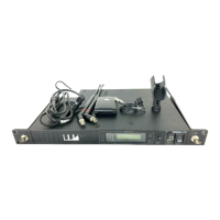
Transmitter Input Clip
The following warning displays on the receiver LCD panel when the transmitter
input is clipped:
To correct, attenuate the signal source. If the source cannot be attenuated
while using a bodypack transmitter, select
INPUT PAD from the main menu to
attenuate the input signal 12 dB.
Mic. Offset
Use this to compensate for signal level differences between transmitters that
share the same receiver.
Set the offset gain on a low signal level transmitter to match a louder transmit-
ter:
Utility > Mic.Offset
Note: For normal gain adjustments, use the receiver gain buttons.
Mute
To mute the audio, use Wireless Workbench or a third-party control device.