6
ULXD4
Digital Wireless Receiver
sync
push
control
ENTER
EXIT
SCAN
RF
A B
OL
OL
gain poweraudio
12V OUT
150 mA
12V OUT
150 mA
ULXD2ULXD2
mic / linemic / linepowerpowerantenna . Bantenna . B antenna . Aantenna . A
15V 0.6A
inst / auxinst / aux
line
mic
www.shure.com
25
L5 644-800 MHz
2
3
3
4
4
5
5
1
1
1
8
8
9
10
11
6
6
7
7
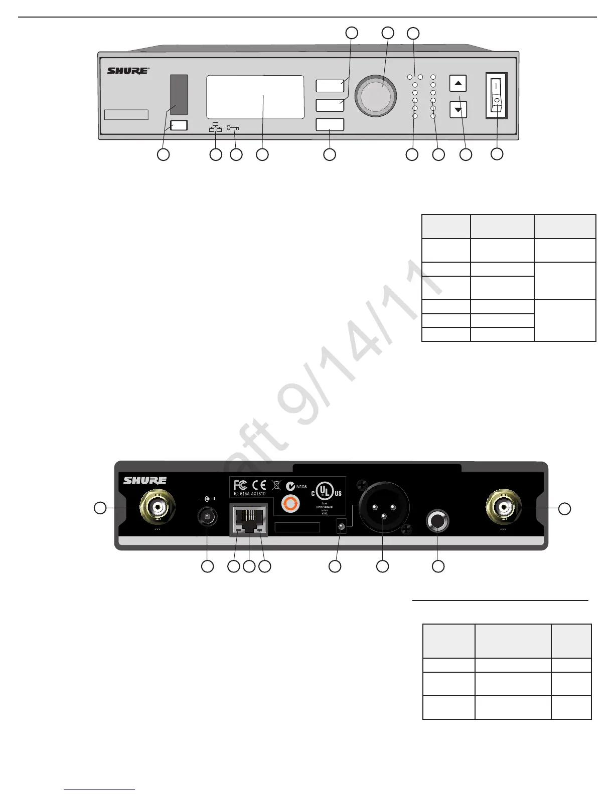
Front Panel
① Sync Button
Press the sync button while the receiver and
transmitter IR windows are aligned to transfer
settings from the receiver to the transmitter
② Infrared (IR) Sync Window
Sends IR signal to the transmitter for sync
③ Network Icon
Illuminates when the receiver is connected with
other Shure devices on the network. IP Address
must be valid to enable networked control
④ Encryption Icon
Illuminates when AES-256 encryption is
activated:
Utilities > Encryption
⑤ LCD Display
Displays settings and parameters
⑥ Scan Button
Press to find the best channel or group
⑦ Menu Navigation Buttons
Use to select and navigate through parameter
menus
Back Panel
① RF Antenna Diversity Input Jack (2)
For antenna A and antenna B.
② Power Supply Jack
Connect the supplied 15 V DC external power
supply
③ Network Speed LED (Amber)
•Off = 10 Mbps
•On = 100 Mbps
④ Ethernet Port
Connect to an Ethernet network to enable
remote control and monitoring
⑤ Network Status LED (Green)
•Off = no network link
•On = network link active
•Flashing = network link active, flash rate
corresponds to traffic volume
⑥ Mic/Line Switch
Applies a 30 dB pad in
mic position (XLR output
only)
⑦ Balanced XLR Audio Output
Connect to a mic or line level input
⑨ Balanced 1/4” (6.35 mm) TRS Audio Output
Connect to a mic or line level input
Receiver
12
⑧ Control Wheel
Push to select menu items for editing, turn to
edit a parameter value
⑨ RF Diversity LEDs
Indicate antenna status:
•Blue = normal RF signal between the receiver
and transmitter
•Red = interference detected
•Off = No RF connection between the receiver
and transmitter
Note: the receiver will not output audio unless
one blue LED is illuminated
⑩ RF Signal Strength LEDs
Indicate the RF signal strength from the
transmitter:
•Amber = Normal (-90 to -70 dBm)
•Red = Overload (greater than -25 dBm, see
Troubleshooting)
⑪ Audio LEDs
Indicate average and peak audio levels:
LED
Audio Signal
Level
Description
Red (6) -0.1 dBFS
Overload/
limiter
Yellow (5) -6 dBFS
Normal peaks
Yellow/
Green (4)
-12 dBFS
Green (3) -20 dBFS
Signal PresentGreen (2) -30 dBFS
Green (1) -40 dBFS
⑫ Gain Buttons
Adjust channel gain
⑬ Power Switch
Powers the unit on or off
Receiver Output Gain
Output
Jack
Output Level
(system gain = 0)
Full
Scale
Output
1/4” TRS 0 dB (unity) +12 dBV
XLR (line
setting)
+6 dB +18 dBV
XLR (mic
setting)
-24 dB -12 dBV
2