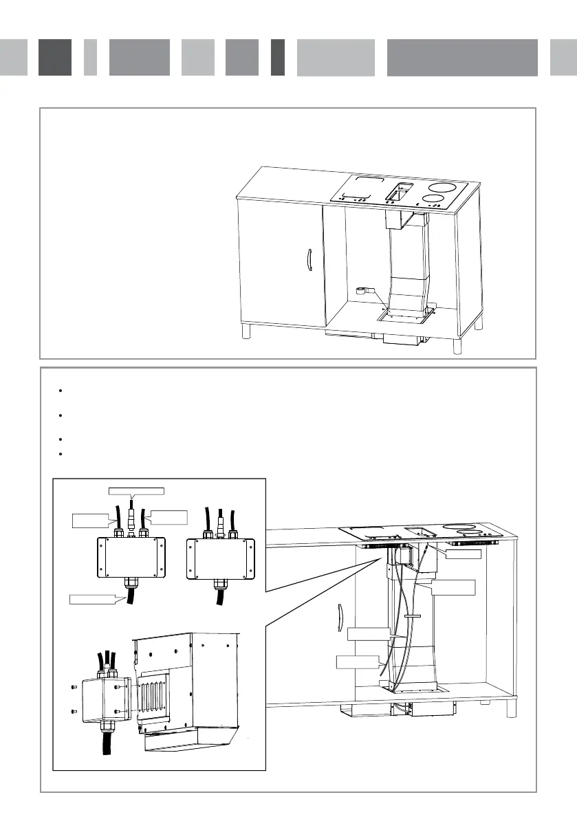
Fig.14
Installation instructions for the air duct
Connect the other end of the ducting channel to the air inlet of the fan system, secure it in place with two
ST4 * 10 screws and seal with aluminium tape.
18
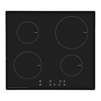
Fig.15
Wiring instructions
Plug the extractor power supply into the corresponding junction box socket and tighten.
Connect the power supply of the extractor.
Connect the fan system signal line to the extractor switch on the underside of the induction hob.
Once connected, fix the wires with a wiring harness (not included). Please note illustration is schematic (Fig. 15).
Make sure the wiring is secure.
Fix the junction box to the left side of the extraction box using ST4 * 13 screws in the accessory bag.
induction hob
power cable
junction box
induction hob
power cable
Main power cable
extractor power cable
Main power cable
extractor power
cable
signal line of
the fan system
switch line