6 -
TRI
12
13
20
14
15
16
17
18
22
D
21
23
30
28
22
29
27
F
E
25
3
24
37
36
27
29
26
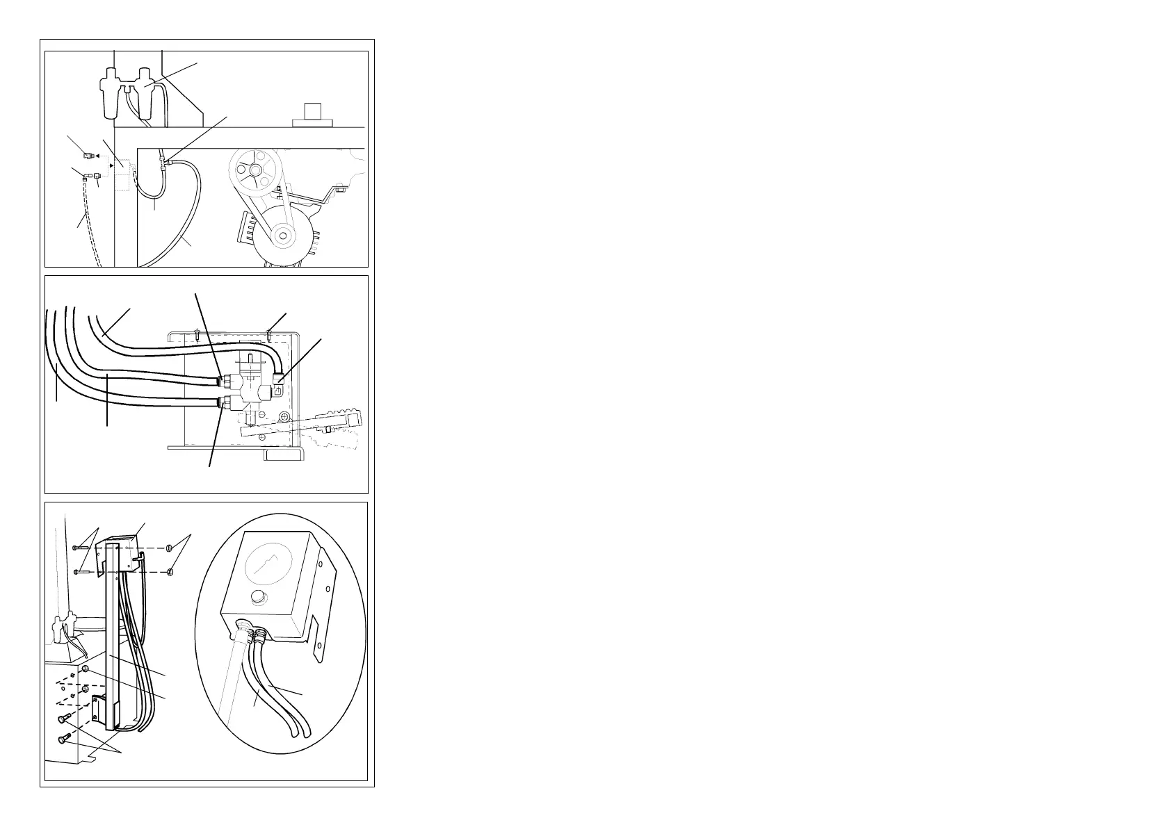
4) Fissare il serbatoio (3, Fig. A) alla carcassa mediante le due viti
M 10x20 (7, Fig. A) e i due dadi M 10 (4, Fig. A).
5) Fissare il tubo (9, Fig. A) proveniente dall'anello di gonfiaggio
al raccordo (10, Fig. A) del serbatoio utilizzando l'apposita fa-
scetta (11, Fig. A).
6) Smontare dalla valvola di gonfiaggio rapido (12, Fig. D) il rac-
cordo con dado (13, Fig. D) e montare al suo posto il raccordo
M-F 1/4" - 1/4" (14, Fig. D) fornito nel kit.
7) Montare sul raccordo M-F 1/4" - 1/4" il raccordo a L 1/4" 8/6
(20, Fig. D) fornito nel kit, avendo cura di orientarlo verso il basso.
8) Tagliare il tubo (15, Fig. D) che collega la valvola (12, Fig. D) al
gruppo filtro/lubrificatore (16, Fig. D) ed inserire il raccordo a T
(17, Fig. D) come mostrato in Fig. D.
9) Collegare un capo del tubo 8-6 lungo 720 mm (18, Fig. D),
fornito nel kit, all'uscita rimasta libera sul raccordo a T (17, Fig. D).
10) Collegare l'altro capo del tubo al raccordo a L (19, Fig. A)
posizionato all'ingresso del serbatoio.
N.B.: Fare passare il tubo attraverso il foro di ø 45 che si trova in
basso sul retro dello smontagomme.
11) Svitare le quattro viti (21, Fig. E) e rimuovere il coperchio della
pedaliera.
12) Collegare un capo del tubo 8-6 lungo 800 mm (22, Fig. E) al
raccordo (23, Fig. E) sulla pedaliera di gonfiaggio.
13) Collegare l'altro capo del tubo al raccordo a L 1/4" 8-6 (20,
Fig. D).
14) Fissare il palo di supporto (24, Fig. F) allo smontagomme utiliz-
zando le viti M 8 x 20 (25, Fig. F) e i dadi M 8 (3, Fig. F) forniti nel kit.
15) Fissare l'unità di lettura (26, Fig. F), utilizzando le viti M 6 x 55
(36, Fig. F) e i dadi autobloccanti M 6 (37, Fig. F), al palo di sup-
porto (24, Fig. F).
16) Collegare il tubo (27, Fig. F) proveniente dall'unità di lettura al
raccordo (28, Fig. E) sulla pedaliera di gonfiaggio.
17) Collegare l'altro tubo (29, Fig. F) proveniente dall'unità di let-
tura al raccordo (30, Fig. E) sulla pedaliera di gonfiaggio.
4) Fix the air tank (3, Fig. A) to the cabinet using two M 10x20 (7,
Fig. A) screws and two M 10 nuts (4, Fig. A).
5) Attach the hose (9, Fig. A) from the inflating ring to the fitting
(10, Fig. A) on the air tank and fix with the hose clamp (11, Fig.
A) in the installation kit.
6) Detach the fitting with nut (13, Fig. D) from the quick inflation
valve (12, Fig. D) and replace it with the 1/4” M-F fitting (14, Fig.
D) in the installation kit.
7) Install the “L” 1/4” 8/6 fitting (20, Fig. D) from the kit onto the
1/4” M-F fitting making sure it directed downwards.
8) Remove the hose (15, Fig. D) connect the valve (12, Fig. D)
to the filter/lubricator (16, Fig. D) and insert the “T” fitting (17,
Fig. D) as shown in Fig. D.
9) Connect one end of the 8-6 hose 720 mm long (18, Fig. D) in
the kit to the free output on the “T” fitting (17, Fig. D).
10) Connect the other end of the hose to the “L” fitting (19, Fig.
A) at air tank in-take.
NB: Push the hose through the ø 45 hole at the bottom rear
side of the tyre changer.
11) Remove the four screws (21, Fig. E) and remove the cover
from the pedal unit.
12) Connect one end of the 8-6 hose 800 mm long (22, Fig. E)
to the fitting (23, Fig. E) on the inflating pedal unit.
13) Connect the other end of the hose to the 1/4” 8-6 “L” fitting
(20, Fig. D).
14) Fix the mounting post (24, Fig. F) to the tyre changer using
M8x20 screws (26, Fig. F) and M8 nuts (37, Fig. F) in the installa-
tion kit.
15) Install the pressure gauge (26, Fig. F) using M6 x 55 screws
(36, Fig. F) and self-locking M6 nuts (37, Fig. F) to the mounting
post (24, Fig. F).
16) Connect the hose (27, Fig. F) from the pressure gauge to
the fitting (28, Fig. F) on the inflating pedal unit.
17) Connect the other hose (29, Fig. F) from the pressure gauge
to the fitting (30, Fig. E) on the inflation pedal unit.
 Loading...