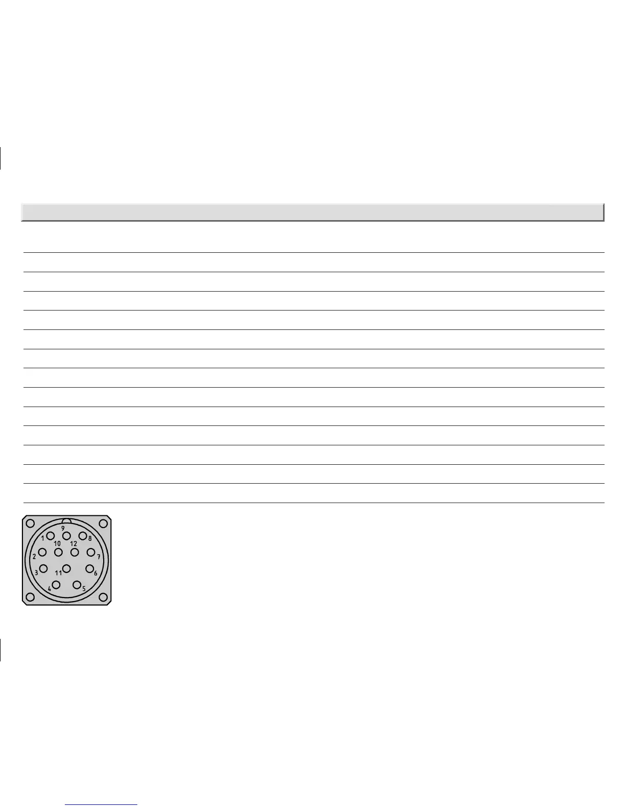
PIN Signal Wire colours (cable outlet) Explanation
1 GND blue earth connection
2 Data + white signal line
3 Clock + yellow signal line
4 R x D + grey RS 422 programming line
5 R x D – green RS 422 programming line
6 T x D + pink RS 422 programming line
7 T x D – black R S 422 programming line
8 Us red supply voltage
9 SET orange electronical adjustment
10 Data – brown signal line
11 Clock – lilac signal line
12 CW/CCW orange / black counting sequence when turning
Screen housing potential
View of the connector M 23 fitted to the encoder body
PIN and wire allocation
0900_sick_MA_8013417.indd 90900_sick_MA_8013417.indd 9 13.05.11 09:5513.05.11 09:55
 Loading...


