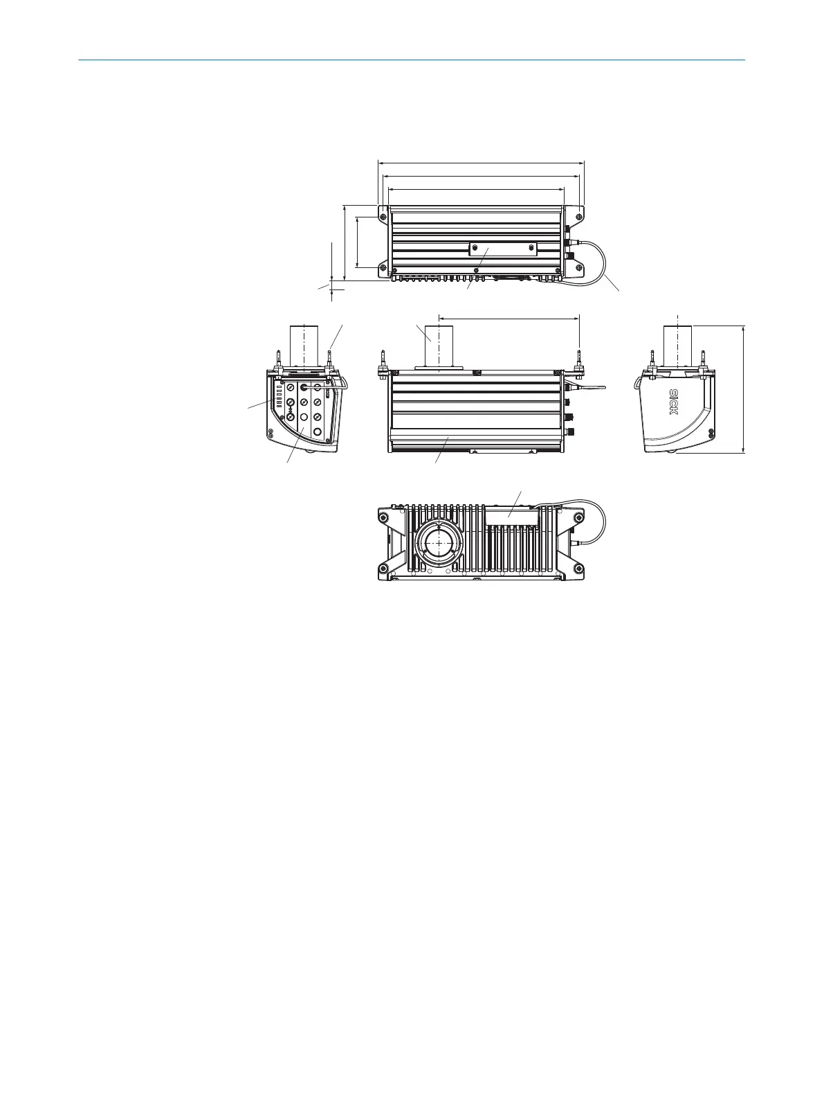
3.3 Product characteristics
3.3.1 Device view
1
9
6
7
2 3
8
4
5
417.1 (
16.42
)
463.5 (
18.25
)
486.8 (
19.17
)
20 (
0.79
)
179 (
7.05
)
120 (
4.72
)
331.5 (
13.05
)
300 (11.81)
ETHERNET
FAN
CAN OUT
CAN IN
1
2
3
Link 3 Act
PWR OUT
PWR IN
LIGHT 1
LIGHT 2
Link 2 Act
Link 1 Act
Ready
Light
Service
Figure 3: structure and device dimensions, unit: mm (inch), decimal separator: period
1
Lens barrel (protective cap included with delivery)
2
Storage media cover with 2 fixing screws (hexagon socket, M4), captive
3
Connecting cable for the fan (depends on variant)
4
Fan
5
Handle
6
Connection mask with M12 electrical connections (the available connections depend on
the variant, protective cap included with delivery for some device types)
7
Status LEDs
8
4 M8 mounting screws with centering pin for mounting the device on the ICI890 illumina‐
tion unit
9
Required maneuvering space for the fan connecting cable (depends on variant)
Optional storage media
The service access is located under the long cover on the rear of the device.
PRODUCT DESCRIPTION 3
8023775/18IM/2020-07-02 | SICK T E C H N I C A L I N F O R M A T I O N | Camera ICD890 Generation 4
15
Subject to change without notice