Status displays
Display LED API name
1
Color Status
Ready Steady - green Device is ready
Steady - red Hardware or software
error
Steady - yellow Firmware or SensorApps
are being installed on the
device. Do not discon‐
nect the power to the
device.
Flashing
(about 1 Hz)
- green/yellow Profinet is configured,
but no successful con‐
nection to a PLC is estab‐
lished.
If there are additional
errors related to the Sen‐
sorApp, the LED flashes
with red color.
Result Programmable
RESULT_LED
red, green, blue,
fuchsia, yellow,
aqua, white
Function defined by user
Light
(LED)
Programmable
LIGHT_LED
red, green, blue,
fuchsia, yellow,
aqua, white
Function defined by user
Function
(Data)
Programmable
FUNCTION_LED
red, green, blue,
fuchsia, yellow,
aqua, white
Function defined by user
LNK TX Flashing - green The device is connected
to a network
LED bar
(0..9)
Programmable
BAR0_LED
BAR1_LED
BAR2_LED
BAR3_LED
BAR4_LED
BAR5_LED
BAR6_LED
BAR7_LED
BAR8_LED
BAR9_LED
green Function for each LED
defined by user
1
For programmable LEDs only
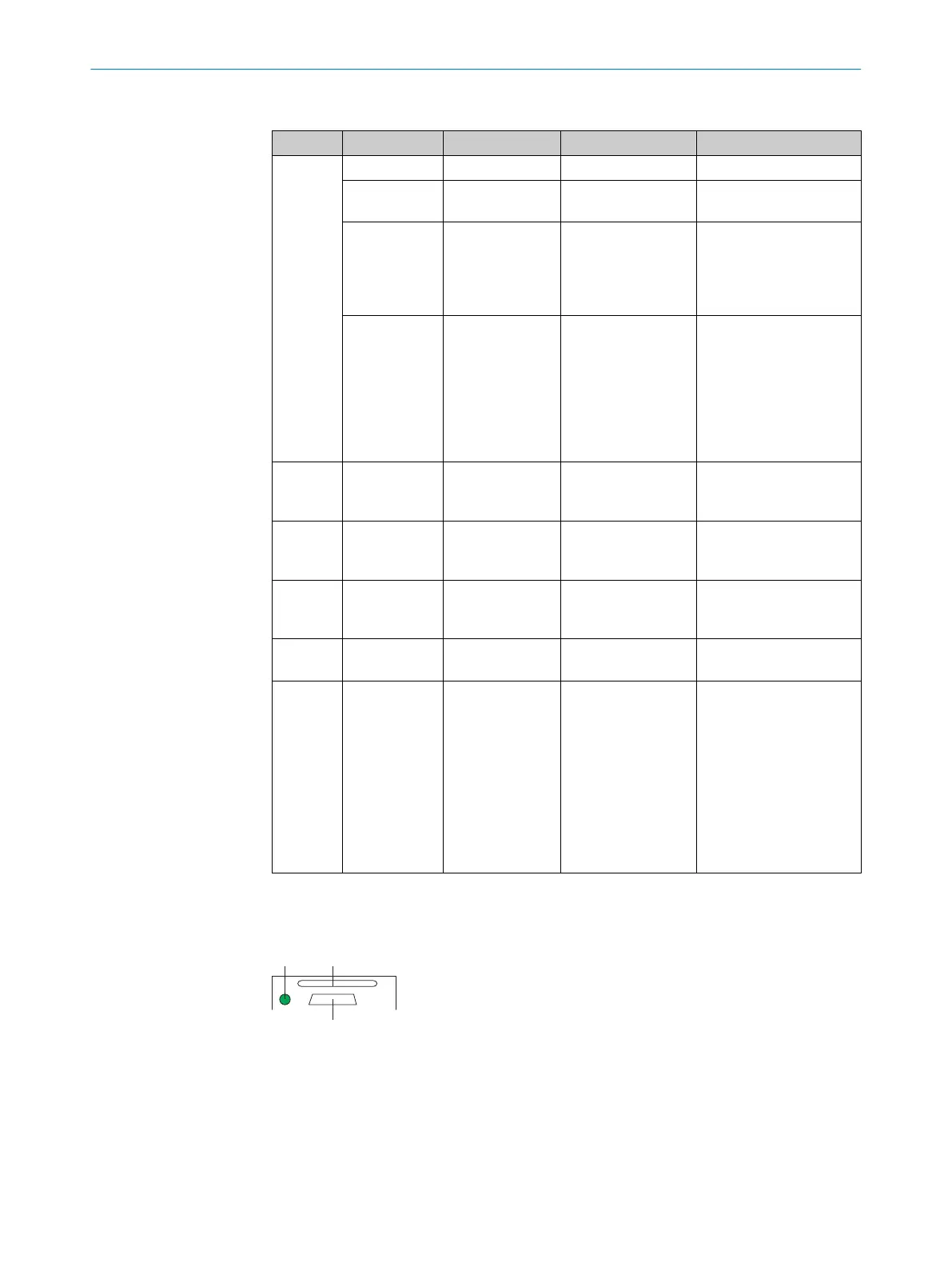
Status display of the microSD memory card
Figure 5: Display under flap on rear of device
á
USB interface
â
Slot for microSD memory card
ã
Display for microSD memory card
PRODUCT DESCRIPTION 3
8024439//2019-06 | SICK O P E R A T I N G I N S T R U C T I O N S | InspectorP621
17
Subject to change without notice